Transcription of INSTALLATION INSTRUCTIONS ELECTRIC SPEEDOMETER
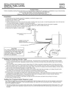
1 General InformationThis ELECTRIC SPEEDOMETER utilizes a LCD to display odometer and trip odometer mileage. Momentarily pressing the Trip/Reset button on the dial window cycles the odometer, trip 1, and trip 2 displays on the LCD. Pressing and holding the Trip/Reset button for more than two seconds while in either trip mode, will reset the trip odometer currently being displayed. The odometer cannot be Meter ELECTRIC speedometers are pre-calibrated. When converting from a cable driven SPEEDOMETER further calibration may not be needed if: 1. The transmission s SPEEDOMETER cable take off is 1000 RPM at 60 MPH (97 km). Most vehicles meet this requirement. 2. The vehicle is equipped with a 16-pulse/revolution sender. 3. The SPEEDOMETER that includes a 2-wire sender is pre-calibrated to 8 pulses/revolution to match this the above conditions have not been met, the SPEEDOMETER must be recalibrated (see calibration section).
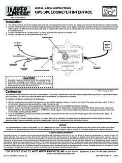
2 Also, if the vehicle s tire size and/or differential ratio has changed, the SPEEDOMETER needs to be : The odometer on this SPEEDOMETER will show some mileage less than 5 miles (8 km). This is a result of factory testing to insure optimum SendersThe SPEEDOMETER is designed to operate with an electrical speed sender. The speed sender signal range must be between 500 and 400,000 pulses/mile (310 and 248,500 pulses/km). Any speed sender or electronic module that meets the following two conditions can be used: 1. Pulse rate generated is proportional to vehicle speed. 2. Output voltage within the ranges listed below: Hall effect sender, 3-wire (5 to 16V) Sine wave generator, 2-wire ( VAC min.) 5V Square wave (CMOS)Recommended Auto Meter Hall effect sender, 3-wire 16 pulses/revolution. 5291 Standard 7/8 18 thread 5292 Ford, plug inMounting 1.
3 Mount SPEEDOMETER in a 33/8" dia. hole. Be careful not to cut the hole too large. 2. Cut a 3/8" dia. hole in the firewall for the SPEEDOMETER wires. Place a rubber grommet in the hole and route the wires through the grommet to the engine compartment. 3. Connect the SPEEDOMETER wires as shown in the wiring sections. 4. Secure the SPEEDOMETER to the dashboard using the provided bracket and the SPEEDOMETER is mounted and wired into the vehicle, the SPEEDOMETER should be tested to verify that the electrical connections are work-ing properly. First, watch the SPEEDOMETER s pointer as the power is applied. The pointer should first move to a midrange position, then down to the 0 position on the dial. This action verifies that power is properly connected to the SPEEDOMETER . The vehicle should be driven some distance to verify the Vehicle Speed Sender (VSS) is connected properly and that the pointer moves.
4 If the pointer does not move off of the zero position, verify that the VSS is connected properly. In some cases calibration may be needed if the pointer does not register speed. Follow the calibration procedure and :If after completely reading these INSTRUCTIONS you have questions regarding the operation or INSTALLATION of your instrument(s),please contact Mopar Technical Support at INSTRUCTIONSELECTRIC SPEEDOMETERWARNINGI ncorrect hookup will damage the SPEEDOMETER and void warranty. Please read these INSTRUCTIONS 4"13 4"311 32"CAUTION!As a safety precaution, the power wire to this product should be fused before connecting it to the 12 VDC power source. We recommend using a 3 Amp automotive fuse inline with the power wire to our : Never apply power to 2-wire speed senderGNDFUSE(SEE CAUTION)DASHLIGHTINGPOWERSIGGND+12 VGNDBack ofspeedometerEngine GroundLAMPOUT+12 VLAMP12V IGNITIONSWITCHBLACK WHITE or TANR emove cap for cruisecontrol cable, otherwise leave cap (SEE CAUTION)3-Wire SenderGROMMETDASHLIGHTINGPOWERSIGGND+12 VGNDBack ofspeedometerEngine GroundLAMPOUT+12 VLAMP12V IGNITIONSWITCHBLACK REDWHITE or CLEARCAUTION!
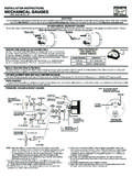
5 As a safety precaution, the power wire to this product should be fused before connecting it to the 12 VDC power source. We recommend using a 3 Amp automotive fuse inline with the power wire to our : The SPEEDOMETER signal output terminal (VSS) produces a +5 volt DC Square wave signal. This signal may be able to be used as a VSS signal with some OEM and aftermarket ECM s and cruise control typical aftermarket 3-wire senderw/ typical aftermarket 2-wire sender (and no computer)Use 20 AWG stranded or heavier wire for hook-upUse 20 AWG stranded or heavier wire for hook-upCalibration To calibrate your electronic SPEEDOMETER : 1) With the power off, push and hold the calibration button (trip/reset button when equipped). While holding the button, start the vehicle and continue to hold the button until the pointer sweeps to full scale and stays at full scale.
6 You may now release the button. 2) Drive to the beginning of a pre-marked 2 mile distance and come to a stop. It does not matter how far away it is to get to this pre-marked 2 mile distance. Do NOT shut the engine off. Push and release the button. The pointer will drop to half scale. 3) Drive the 2 mile distance. The pointer will remain at the half scale mark no matter what speed you drive. If the SPEEDOMETER has a LCD display odometer, it will be normal to see it counting rapidly as it is receiving a speed signal. If you have to stop during the calibration, that is The SPEEDOMETER is simply counting pulses during this ) At the end of the 2 mile distance, come to a complete stop and push and release the button. The pointer will drop to 0 and the calibration is stored. You are now finished with calibration.
7 Remember the accuracy of your 2 mile distance will directly affect the ac-curacy of your 8/7/12 2012 Auto Meter Products, ReplacementRemove the plastic cap on the back of the SPEEDOMETER . Using needle nose pliers, rotate the twist-lock lamp socket counterclockwise to remove. Replace old bulb with GE 168 PERFORMANCE PARTS ARE SOLD AS IS, WITHOUT ANY WARRANTY WHATSOEVER. Implied warranties, including warranties of merchantability or fitness for a particular purpose, are excluded. The entire risk as to quality and performance of such parts is with the buyer. Should such parts prove defective following their purchase, the buyer and not the manufacturer, distributor or retailer, assumes the entire cost of all necessary servicing or repair. Chrysler, Dodge, and Jeep vehicle and parts warranties are voided if the vehicle or parts are used for competition or if they fail as a result of Super Bezel is a registered trademark of Auto Meter Products, (SEE CAUTION)DASHLIGHTINGPOWERSIGGND+12 VGNDBack ofspeedometerEngine GroundLAMPOUT+12 VLAMP12V IGNITIONSWITCHF actory rated power check withOEM to determine if this is a 5V, 6V, 8V, or 12V.
8 Applying higher thenrated can permanently damageV. (SEE CAUTION)DASHLIGHTINGPOWERSIGGND+12 VGNDBack ofspeedometerEngine GroundLAMPOUT+12 VLAMP12V IGNITIONSWITCHNEVER APPLY POWER TO2-WIRE V. !GNDFUSESPEED OUT- LOW SIDE+ HIGH SIDE(SEE CAUTION)DASHLIGHTINGPOWERSIGGND+12 VGNDBack ofspeedometerEngine GroundLAMPOUT+12 VLAMP12V IGNITIONSWITCHFACTORY OR AFTERMARKET COMPUTER OR TRANS OUTLO SIGHIGH SIGW iringWiringWiringw/ most OEM 3-wire (Vehicle Speed Sensor)w/ most OEM 2-wire (When no computer involved)w/ most OEM 2-wire using computer or trans controllerUse 20 AWG stranded or heavier wire for hook-upUse 20 AWG stranded or heavier wire for hook-up* SEE NOTENOTE: Pin orientation may not be actual.