Transcription of INSTALLATION TUNING AND TROUBLESHOOTING MANUAL
1 Part Number s 504-13 Pro-Jection 4D, 650 CFM 504-12 Pro-Jection 4D, 700 CFM Part Number s 504-23 Pro-Jection 4Di, 650 CFM 504-22 Pro-Jection 4Di, 700 CFM 504-21 Pro-Jection 4Di, 900 CFM INSTALLATION TUNING AND TROUBLESHOOTING MANUAL NOTE: These instructions must be read and fully understood before beginning INSTALLATION . If this MANUAL is not fully understood, INSTALLATION should not be attempted. Failure to follow these instructions, including the pictures may result in subsequent system failure. TABLE OF CONTENTS: 2 INTRODUCTION .. 4 CHOOSING THE RIGHT SYSTEM .. 4 WARNINGS, NOTES, AND NOTICES .. 5 PARTS IDENTIFICATION .. 5 ADDITIONAL PARTS REQUIRED FOR INSTALLATION .. 9 TOOLS REQUIRED FOR INSTALLATION .. 9 REMOVAL OF EXISTING FUEL SYSTEM .. 9 PRO-JECTION SYSTEM INSTALLATION .. 10 Throttle Body .. 10 Throttle Connections.
2 10 Vacuum Line Connections .. 11 Fuel Pump INSTALLATION .. 11 Dual Tank INSTALLATION .. 12 Fuel Pump Filter .. 14 Throttle Body Fuel Filter .. 14 Return Line INSTALLATION .. 14 Inlet Fuel Line INSTALLATION .. 15 Oxygen Sensor INSTALLATION .. 15 Oxygen Sensor Function, Theory, and Use .. 15 Oxygen Sensor Mounting Procedure .. 15 electronic Control Unit (ECU) Mounting .. 16 Engine Wiring Harness .. 16 Coolant Temperature Sensor .. 16 Manifold Absolute Pressure (MAP) Sensor .. 17 ELECTRICAL CONNECTIONS .. 17 Air Charge Temperature Sensor .. 18 Coolant Temperature Sensor .. 18 Throttle Position Sensor (TPS) .. 18 Idle Air Control (IAC) Motor .. 18 Injectors .. 18 Manifold Absolute Pressure (MAP) Sensor .. 18 Oxygen Sensor .. 18 Fuel Pump .. 18 ignition /Spark Control .. 19 Fuel Pump and System Power Relays.
3 19 System Power .. 19 Tachometer/ ignition .. 19 Oil Pressure Switch .. 20 MECHANICAL CHECKOUT BEFORE STARTING ENGINE .. 20 PRO-JECTION SYSTEM TUNING THEORY AND PHILOSOPHY .. 21 TUNING Goals .. 21 Oxygen Sensor Effect on Performance .. 21 Engine Configuration Related Concerns .. 21 GETTING STARTED TUNING AND PROGRAMMING (D SYSTEM) .. 23 TUNING Tips .. 23 Calibration Module Controls .. 23 TUNING and Adjustment Procedures for a D System .. 23 TABLE OF CONTENTS: (cont.) GETTING STARTED TUNING AND PROGRAMMING (Di SYSTEM) .. 26 3 Software INSTALLATION and Software Operational Description .. 26 Windows 95 .. 26 Windows .. 26 Dos Install .. 27 Mapview .. 27 Data Monitor .. 27 EEprom Programming .. 28 File .. 28 Edit .. 29 Graph .. 31 Print .. 31 Communications .. 32 TUNING Tips for a Di System .. 32 TUNING Tips for a Di System With an Oxygen Sensor (closed loop).
4 32 Other General TUNING Tips for a Di System (closed and open loop) .. 32 TUNING and Adjustment Procedures With a Di System .. 33 OPERATION OF THE PRO-JECTION SYSTEM .. 36 Normal Starting Procedure .. 36 Normal Operation and Use .. 36 MAINTENANCE AND STORAGE .. 36 GENERAL TROUBLESHOOTING .. 37 Testing and Adjusting Fuel Pressure .. 38 TESTING AND TROUBLESHOOTING ELECTRICAL COMPONENTS .. 38 Testing Relays .. 38 Testing the Manifold Absolute Pressure (MAP) Sensor .. 38 Throttle Position Sensor (TPS) Adjustment .. 39 Testing Idle Air Control (IAC) Motor .. 40 Testing Coolant Temperature Sensor .. 40 Testing Air Charge Temperature Sensor .. 40 Testing the Oxygen Sensor .. 40 INTRODUCTION holley Performance Products has written this MANUAL for the INSTALLATION of the PRO-JECTION 4D and 4Di fuel injection system. This MANUAL contains all the information needed to install this system.
5 Please read all the WARNINGS, NOTES, and TIPS, as they contain valuable information that can save you time and money. It is our intent to provide the best possible products for our 4 customer; products that perform properly and satisfy your expectations. Should you need information or parts assistance, please contact our technical service department at 1-270-781-9741, Monday through Friday, 7 to 5 Central Time. By using this number, you may obtain any information and/or parts assistance that you may require. Please have the part number of the product you purchased when you call. WARNING! The PRO-JECTION 4D and 4Di systems consist of a number of sophisticated components. Failure of any one component does not constitute, nor does it justify, warranty of the complete system. Individual service items are available for replacement of components. If assistance is required or if you need further warranty clarification, you can call holley Technical Service at the number shown above.
6 WARNING! To preserve warranty, these instructions must be read and followed thoroughly and completely before and during INSTALLATION . It is important that you become familiar with the parts and the INSTALLATION of the PRO-JECTION system before you begin. Failure to read and understand these instructions could result in damage to PRO-JECTION components that are not covered by the warranty and could result in serious personal injury and property damage. WARNING! For closed loop systems using an oxygen sensor, use only unleaded fuels with this product. Use of leaded fuels will destroy the oxygen sensor and will result in incorrect exhaust gas oxygen readings and improper fuel delivery. Failure to follow these directions does not constitute the right to a warranty claim. WARNING!
7 Failure to follow all of the above will result in an improper INSTALLATION , which may lead to personal injury, including death, and/or property damage. Improper INSTALLATION and/or use of this or any holley product will void all warranties. WARNING! Use of some RTV silicone sealers will destroy the oxygen sensor used with this product. Ensure the RTV silicone sealant you use is compatible with oxygen sensor vehicles. This information should be found on the oxygen sensor package. CHOOSING THE RIGHT SYSTEM: To ensure that you have purchased the correct PRO-JECTION kit for your application, check to be sure that the kit you purchased is listed beside your engine s horsepower. For best results in the event of an application overlap, the correct kit choice is the one that the engine horsepower is more centered in the application. For example, if your engine is rated at 275 hp, look at the chart below, you will notice that there are 4 kits that could fit your application.
8 275 hp. is near the upper limit of Kit # s 504-13 and 504-23. 275 hp. is more centered in the horsepower range of Kit # s 504-12 and 504-22. The correct choice would be one of the kits listed in the 225 to 400 horsepower range. HORSEPOWER KIT PART NUMBER 150 - 300 hp .. 504-13 PRO-JECTION 4D, 650 CFM 504-23 PRO-JECTION 4Di, 650 CFM 225 - 400 hp .. 504-12 PRO-JECTION 4D, 700 CFM 504-22 PRO-JECTION 4Di, 700 CFM 350 - 500 hp .. 504-21 PRO-JEDTION 4Di, 900 CFM Kit numbers 504-12 and 504-13 are referred to as D systems. The D unit comes with a calibration module for modifying the fuel maps. Optional monitoring software can be purchased and a PC can be used to monitor system operation of the PRO-JECTION D system but can not be used to make adjustments.
9 Kit numbers 504-21, 504-22 and 504-23 are referred to as Di systems. The Di unit is intended to be adjusted by a laptop PC. A calibration module is not supplied with the unit but is available as an option. All software to modify the fuel maps is supplied with the Di unit. The Di unit has the capability of ignition spark control. The unit is also compatible with both the GM, Ford and holley electronic advance ignitions. WARNINGS, NOTES, AND NOTICES WARNING! For the safety and protection of you and others, the INSTALLATION , adjustment, and repair must be performed only by a trained mechanic having adequate fuel system experience. It is particularly important to remember one of the very basic principles of safety: fuel vapors are heavier than air and tend to collect in low places where an explosive fuel/air mixture may be ignited by any spark or flame 5 resulting in property damage, personal injury and/or death.
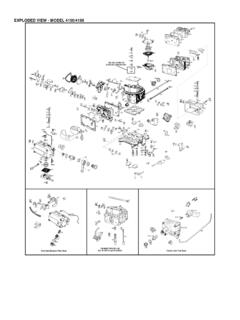
10 Extreme caution must be exercised to prevent spillage and thus eliminate the formation of such fuel vapors. WARNING! This type of work MUST be performed in a well-ventilated area. Do not smoke or have an open flame present near gasoline vapors or a explosion may result. PARTS IDENTIFICATION ITEM DESCRIPTION QTY SERVICE PART 1 TBI Assembly 650 CFM Complete 1 500-18 TBI Assembly 700 CFM Complete 1 500-17 TBI Assembly 900 CFM Complete 1 500-16 2 electronic Control Unit (ECU) D Systems 1 534-40 electronic Control Unit (ECU) Di Systems 1 534-39 3 Interactive Mapping Software Di Only 1 534-44 4 Wiring Harness 1 534-43 5 DB-9 Computer Cable Di Only 1 534-45 6 Calibration Module D Only 1 534-41 7 Fuel Pump 1 512-104 8 Fuel Pump Clamp 1 N/A 9 Metal Fuel Filter 1 562-1 10 Plastic Fuel Filter 1 562-3 11 Fuel Filter Clamp 1 108-10 12 Fuel Pump Block-Off Plate & Gasket 1 12-813 13 Oxygen Sensor 1 43-106 14 MAP Sensor 1 538-13 15 Coolant Temperature Sensor 1 534-2 16 Air Cleaner Adapter 1 17-14 17 Air Cleaner Gasket 1 108-4 18 Distribution Ring 1 508-12 19 Flange Gasket 1 108-10
