Transcription of Installation Instructions for Programming Interfaces
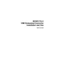
1 1 / 3 Specifications are subject to changes without notice. April 22, 2015 Installation Instructions for Programming Interfaces Tel: 86-571-56565800 Fax: 86-571-86601139 For Inventronics programmable drivers & control modules, settings may be changed through the corresponding Programming interface which must be installed on a PC and connected to the programmable device through its programmer as illustrated in the diagrams below. 1. Obtain the correct programmer for the device to be programmed, along with its datasheet: a. PRG-MUL2 for non-DMX drivers and control modules (The older SDD-AAPNP Multi Programmer works also for 0-10V drivers.) b. PRG-DMX for DMX drivers c. PRG-CSIM for the CSIM-100 Control Signal Integration Module 2. Device Driver Installation (if the Inventronics driver has never been installed) Download & run the Programming interface Driver from (also accessible from by selecting Sales & Services, Downloads) 3.
2 Framework Installation (skip for Windows , where it s already included) Install the software from Microsoft website ( ) 4. Programming interface Installation Download the correct Programming interface for the programmer from (also accessible from by selecting Sales & Services, Downloads) Note: The software Installation may be interrupted by virus checking software. If this happens, disable the virus checking software, install the Programming interface , then re-enable the virus checking software. 5. Referring to the Programming connection diagram in the datasheet of the device to be programmed, connect the PC, programmer, device to be programmed, and any other equipment shown. 6. Open the icon that was automatically added to the desktop. 7. If applicable, select the device type to be programmed, then press Startup.
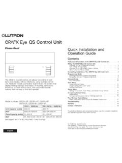
3 Example: Select 0-10V dimming driver if the driver s suffix starts with D like in LUD-060S150 DSF. 8. Proceed with Programming according to the datasheet of the programmer and device to be programmed. Perform a Write Driver operation to load the selected settings into the driver, then Read Driver will display the exact values stored (which may be slightly different from the values entered). If either of these operations fail, uncheck the Matching box, ensure the correct Series and Model numbers are selected, then try again. 2 / 3 Specifications are subject to changes without notice. April 22, 2015 Installation Instructions for Programming Interfaces Tel: 86-571-56565800 Fax: 86-571-86601139 Example Programming Connection Diagram for an Intelligent LED Driver (see driver datasheet for the applicable diagram) Example Programming Connection Diagram for a Control Module 3 / 3 Specifications are subject to changes without notice.
4 April 22, 2015 Installation Instructions for Programming Interfaces Tel: 86-571-56565800 Fax: 86-571-86601139 Revision History Change Date Rev. Description of Change Item From To 2014-12-03 A Release / /