Transcription of Installation Instructions NLV-600, NLV-1000, NLV-1500
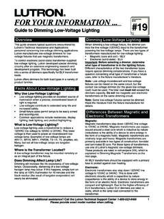
1 Low Voltage Dimmers Installation Instructions NLV-600, NLV-1000, NLV-1500 . Please Leave for Occupant 120 VAC, 60Hz Table Of Contents Multi-phase Applications: In multi-phase Package Contents .. 1 applications, use a separate neutral for each phase Important Notes .. 1 containing a dimming circuit. For more information, Single Unit Installation .. 1 call the toll-free Lutron Technical Assistance Multigang Installation - Hotline for Application Note 17, "Common Neutral No side Sections Removed .. 2 Interaction". Multigang Installation - Side Section Removed .. 3 Short Circuit Check: Check new Installation for Installation Assistance .. 4 short circuits prior to Installation . With power OFF, use a single pole switch and connect appropriate wires to hot wire and lamp. Turn power ON.
2 If lights Package Contents: do not work or breaker trips, a short is present. Slider Correct wiring and check circuit again. Install dimmer only when short is no longer present. Wire Connectors: Wire connectors provided can be Control Mounting Screws used to join one 10-, 12-, 14-, 16-, or 18-gauge wire Shaft with one or two 12- or 14-gauge wires. Use them with copper wire only. Switchbox Location: A single-gang switchbox (3". Wire Control Connectors high x 2" wide x 21/2" deep) will service all individual Faceplate Nova dimmers. Allow a minimum space of 41/2". above and below the dimmers for proper heat dissipation. These dimmers are designed for use Important Notes where ambient temperature is between 0oC to 40oC. Please Read Before Installation (32oF to 104oF). Transformer Information: Use with core and coil (magnetic) low-voltage transformers only.
3 For more Multigang Installations: Lutron offers a multigang information, call the toll-free Lutron Technical faceplate to simplify and improve the appearance of Assistance Hotline for Application Note 19, "Guide your Installation . A multigang mounting frame is to Dimming Low-Voltage Lighting". provided with each standard faceplate to ensure proper alignment of the dimmers, easy application of Caution: Operation of a dimmer low voltage circuit the faceplate, and a flat surface. with all lamps inoperative or removed may result in current flow in excess of normal levels. To avoid Faceplate Cleaning: For best results, use mild possible transformer overheating and premature cleaner and damp cloth. Do not use ammonia-based transformer failure, Lutron strongly recommends the cleaner.
4 Following: a. Do not operate dimmed low-voltage circuits Single Unit Installation without operative lamps in place. b. Replace burned-out lamps as quickly as possible. 1. Turn power OFF at fusebox or circuit breaker. Wiring with power on can result in personal injury. c. Use transformers that incorporate thermal Damage to product caused by wiring with power on protection or fuse transformer primary windings to voids warranty. prevent transformer failure due to overcurrent. 2. Remove faceplate from dimmer to prevent Lamp Type: Use incandescent low-voltage lamps in damage and to access mounting holes. Pull out at combination with a low-voltage transformer or 120V top and bottom edges, plate will snap off. incandescent lamps. 3. Strip insulation from dimmer wires and from wires Caution: To avoid overheating and possible to which dimmer is to be connected as follows: damage to other equipment, do not install to 1/2" for 10, 12, and 14 gauge wire control receptacles, fluorescent lighting fixtures, 5/8" for 16 and 18 gauge wire motor-operated appliances, or transformer supplied appliances.
5 1/2" or 5/8". This product is covered by one or more of the following patents: 4,876,498;. 4,954,768 and corresponding foreign patents. and foreign patents pending. Lutron and Nova are registered trademarks. 1. 1997 Lutron Electronics Co., Inc. 4. Use wire connectors provided to make the 7. Turn power ON. Slide shaft up to increase light following connections: intensity, down to decrease light intensity and turn OFF. a. Green or bare ground wire to ground in the wallbox. Note: If a bare copper or green ground wire 8. Minimum light intensity is preset. To adjust, use is not in the wallbox, contact a licensed electrician. the screwdriver provided to turn the trimpot screw b. Black control lead to 120 VAC lead. (inside trimpot shaft) clockwise to increase light level and counterclockwise to decrease light level.
6 C. Yellow lead to one transformer primary lead. 9. Install slider on faceplate by firmly d. White lead to neutral, along with the other pressing at top, center, and bottom to snap tabs into transformer primary lead. See figures A and B. Be place. See Figure D. sure copper conductor is not exposed. Tabs To Fusebox or Circuit Breaker Neutral Black Faceplate Hot White Press plate Until Tabs Snap In Figure D. Snap on Faceplate Neutral Yellow To Lighting Multigang Installation - Load No Side Sections Removed (No Derating Required). Ground Green Dimmed Leg or Bare In multigang installations several dimmers or controls are grouped horizontally in one ganging switchbox or Figure A. Switchbox Wiring in a series of interconnected switchboxes. Lutron offers multigang faceplates to simplify and improve Full Voltage Variable Voltage the appearance of these installations.
7 A multigang mounting frame is provided with each standard Black Yellow multigang faceplate to ensure proper alignment of dimmers, easy application of the faceplate, and a flat Green or surface for the Installation . Refer to multigang 120V Bare instruction sheet supplied with multigang faceplate. 60Hz Magnetic Ground Installation of dimmers without removing side Transformer(s). sections allows operation at full capacity ( , no White Lamps derating is required). Follow Instructions below. For retrofit installations, side sections can be removed to fit existing switchboxes. See "Multigang Installation - Figure B. Wiring Diagram Side Sections Removed" on page 3. 5. Carefully push wires into switchbox allowing room 1. Determine the number of switchboxes necessary for dimmer backbox.
8 By using the Switchbox Requirement Chart (Table A). When ganging any combination of small dimmers 6. Mount dimmer to switchbox using two screws (NLV-600) and large dimmers (NLV-1000 and NLV- provided and center mounting holes. See Figure C. 1500), place all small dimmers at one end of the Unit must be mounted vertically. gang and all large dimmers at the other. Table A. Switchbox Requirement Chart Trimpot Shaft No Side Sections Removed Slider Shaft Number of Small Controls 0 1 2 3 4 5 6. 0 0 1 1+1* 4 4+1* 7 1+7*. Number 1 1 3 5 6 8 9 11. of Large 2 4 6 7 9 10 12 13. Controls 3 6 8 10 11 13 14 16. Offset Mounting Holes Center Mounting Holes 4 9 11 12 14 15 17 18. Figure C. Front View-Single Unit Installation *See item #2. 2. 2. When ganging an even number of small dimmers use gangable 3" x 2" switchboxes.
9 Do not use Multigang Installation -- plaster rings or gangbox covers. You need one Side Sections Removed (Derating Required). switchbox in addition to the total number of controls in order to provide space for faceplates ( 4 In multigang installations several dimmers or controls dimmers require 5 switchboxes). Place additional are grouped horizontally in one ganging switchbox or switchboxes 3/4" apart from other switchbox(es) to in a series of connected switchboxes. Lutron offers provide space for faceplate(s). See Figure E. multigang faceplates to simplify and improve the appearance of this Installation . A multigang mounting frame is provided with each standard multigang faceplate to ensures proper alignment of dimmers, easy application of faceplate, and a flat surface for the Installation .
10 Refer to multigang instruction sheet supplied with multigang faceplate. Four-Gang Gangable 3. /4" Space Single-Gang 1. Derating is required when side sections are Switchbox (use chase Gangable removed. Ensure safe operation by using derating nipple) Switchbox chart (Table B) to determine maximum possible load Figure E. Switchbox Positioning Four-Gang Controls when side sections are removed. Match dimmer size and number of side sections removed with maximum 3. Turn power OFF. safe load size. 4. Wire each dimmer according to step 1-4 in Table B. Derating Chart-Maximum Amperage Load "Single Unit Installation " on page 1. NLV-600 NLV-1000 NLV-1500 . 5. Install dimmers in switchbox(es) using screws Max. VA (Amps) 600 (5) 1000 ( ) 1500 ( ). provided. Begin with small dimmers and use center Max.