Example: stock market
INSTALLATION INSTRUCTIONS PUSH BUTTON START SYSTEM
ACC / IGN / STR red wires connected to a high current fused or circuit breaker protected circuit. STEP 7 1. Wire the main harness. a. The red wire from the main harness should be terminated to the dedicated 3 amp constant hot fused circuit. b. The black wire should be terminated to an adequate ground point. c.
Tags:
Information
Domain:
Source:
Link to this page:
Documents from same domain
Ford Installation Instructions - jegs.com
www.jegs.comMarch 21, 2006 Ford Performance Transmission Instructions 1 BD PERFORMANCE TRANSMISSION Ford Installation Instructions ... product returned prepaid with a complete service history and proof of purchase. A valid proof of purchase is a dated bill of sale. Repaired or replaced product will be returned to the customer freight collect.

INSTALLATION INSTRUCTIONS 426 / 472 / 528 CID HEMI …
www.jegs.comThe Hemi Crate engines are assembled entirely from NEW Chrysler engineered components. The following is a list of potential issues which may arise during installation and the initial "fire up” process. If any problems arise, contact the Mopar Direct Connection Tech Line at 1-888-528
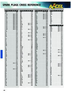
SPARK PLUGS CROSS REFERENCE - jegs.com
www.jegs.com1.This application listing is to be used as a guide only. Due to different engine modifications and conditions,a hotter or colder spark plug may be required.

HOLLEY SUPERCHARGER INSTALLATION …
www.jegs.comThe Ultra Charger Cam for big block Chevrolet has a slightly rough idle, acceptable vacuum for most street applications and outstanding mid and top range power.

WHEEL NUT TORQUE SPECIFICATIONS (shown in ft. …
www.jegs.comLEXUS All Models Except: 2010-90 76 All Models Except: 2012 103 CT, ES, GS, IS, LS 2013 76-84 CT200h, ES350 2012-11 76 GS305 2013 76 GS350, GS450h, GS460 2011 76 HS250h, IS250, IS250c, IS350, IS350c, ISF 2012-11 76 IS250c, IS350c, ISF 2013 76 LS460, LS600h 2012-07 103 LINCOLN Continental 2002-90 85-105 LS 2006-00 100 …
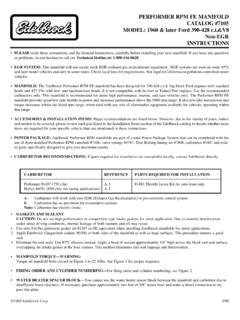
PERFORMER RPM FE MANIFOLD CATALOG #7105 …
www.jegs.comA- Carburetor will work with non-EGR ... Remove dowel pins from end seal surface on Ford and Chrysler products. Use grip pliers for removal.
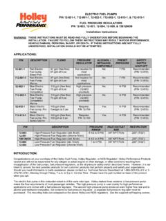
Holley 12-804 Fuel Pressure Regulator Installation ...
www.jegs.com2 PUMP MOUNTING AND INSTALLATION: The best location for mounting any electric fuel pump is the rear of the vehicle. The inlet and outlet of the pump must be
INTRODUCTION TABLE OF CONTENTS - jegs.com
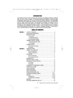
www.jegs.com3 Edelbrock Performer Series Carburetor Owner’s Manual 8/94 METERING SYSTEMS The Edelbrock carburetor has three (3) basic systems that meter fuel to the engine: The Idle System, Primary Main System, and Secondary Main System.

HYFIRE IV SERIES OF ELECTRONIC IGNITION CONTROLS
www.jegs.comThe HYFIREfi IV Electronic Ignition Controls are designed to work with most original equipment ignition coils. For optimum performance use the Mallory PROMASTER fi Coil Part

Recommended Crate Engine Start-Up Procedure
www.jegs.comRecommended Crate Engine Start-Up Procedure 1. SAFETY FIRST! If the car is on the ground, be sure the emergency brake is set, the wheels are chocked, and the transmission cannot fall into gear.
Related documents

Installation Instructions Features and Specifications for ...
assets.bluesea.comFull Installation Diagram 425 Sequoia Driveswitch may affect accuracy because of voltage drop along current carrying conductors. Bellingham, WA 98226 USA p 360.738.8230 p 800.222.7617 USA and Canada f 360.734.4195 conductor@bluesea.com www.bluesea.com start accessory run off Recommended (not included) Dual Circuit Plus™ battery switch House ...

MFJ-949E Versa Tuner II Instruction Manual
www.radiomanual.infocircuit) configurations. ... Install the MFJ-949E between the transmitter and antenna as shown in the diagram above. Use a 50 ohm coaxial cable to connect the transmitter or transceiver to the SO-239 (UHF female) labeled TRANSMITTER on the back of the tuner. ... instructions shows typical capacitor settings that can be used for each amateur band.

Wiring Kit Instructions - American Autowire
www.americanautowire.comCircuit Branch 6 - Headlight Switch Connection Kit This kit is designed to function with a GM style headlight switch. Connections are functionally the same with any other type of headlight switch with the exceptions noted below. Orient the headlight switch connector as shown in the diagram . You will be looking at the front of the

HILUX Electrical Wiring Diagram - Tuning Concepts
www.tuningconcepts.com(All circuit diagrams are shown with the switches in the OFF position.) When troubleshooting any problem, first understand the operation of the circuit where the problem was detected (see System Circuit section), the power source supplying power to that circuit (see Power Source section), and the ground points (see Ground Point section).

WIRE HARNESS INSTALLATION INSTRUCTIONS
www.painlessperformance.comThe contents of these instructions are divided into major Sections, as follows: 1.0 Introduction 2.0 About these instructions 3.0 Contents of PPPI Wire Harness Kit 4.0 Tools needed 5.0 Pre-Installation and General Harness Routing Guidelines 6.0 General Harness Installation Instructions 7.0 GM-Specific Circuit Connection Details

Systems I: Computer Organization and Architecture
home.adelphi.edu• The instructions are stored in computer memory in the same manner that data is stored. • The control unit interprets these instructions and uses the operations code to determine ... Logic Circuit. This allows the Accumulator and Data Register to swap data simultaneously.

Owner’s Manual & Safety Instructions
manuals.harborfreight.comOwner’s Manual & Safety Instructions Save This Manual Keep this manual for the safety warnings and precautions, assembly, operating, inspection, maintenance and cleaning procedures Write the product’s serial number in the back of the manual near the assembly diagram (or month and year of purchase if product has no number)

GRX-TVI Control Interface - Lutron Electronics, Inc.
www.lutron.com• Wiring Diagram A shows a GRX-TVI wired from one distribution panel. If the power requirement of the complete system is less than an MCB/circuit breaker rating and L1/H1 and L2/H2 are both coming from the same phase, one feed can be jumpered inside the enclosure (as shown on Page 3). • Wiring Diagram B shows a GRX-TVI wired from two separate

Chapter 2: Basic Ladder Logic Programming
personal.kent.eduLadder Logic Diagram Example 1 Computer Aided Manufacturing TECH 4/53350 27 Task: Draw a ladder diagram that will cause the output, pilot light PL2, to be on when selector switch SS2 is closed, push button PB4 is closed and limit switch LS3 is open. (Note: no I/O addresses yet.) Thought Process

Wiring Instructions for 60-0-60 Ammeter
www.fwmurphy.comAll instructions refer to viewing from the rear. 1. Disconnect battery ground cable. 2. Connect an 8 AWG (10.0 mm. 2) wire, minimum, with an insulation temperature rating of 220° F (105° C), minimum, from the battery terminal of the alternator to …