Transcription of Installation Instructions Regarding the Gate Operator
1 Installation Instructions Regarding the gate OperatorA) Install the gate Operator only when:1) The Operator is appropriate for the construction and the usage Class of the ) All openings of a horizontal slide gate are guarded or screened from the bottom of the gate to a minimum of 4 feet ( m) above the ground to prevent a 2 1/4inch ( mm) diameter sphere from passing through the openings anywhere in the gate , and in that portion of the adjacent fence that the gate covers in the open ) All exposed pinch points are eliminated or guarded, and4) Guarding is supplied for exposed ) The Operator is intended for Installation only on gates used for vehicles. Pedestrians must be supplied with a separate access ) The gate must be installed in a location so that enough clearance is supplied between the gate and adjacent structures when opening and closing to reduce the risk of entrapment.
2 Swinging gates shall not open into public access ) The gate must be properly installed and work freely in both directions prior to the Installation of the gate Operator . E) -F) Controls must be far enough from the gate so that the user is prevented from coming in contact with the gate while operating the controls. Controls intended to be used to reset an Operator after 2 sequential activations of the entrapment protection device or devices must be located in the line of sight of the gate outdoor or easily accessible controls shall have a security feature to prevent unauthorized ) All warning signs and placards must be installed where visible in the area of the ) For a gate Operator utilizing a non-contact sensor such as a photo beam:1) See Instructions on the placement of non-contact sensor for each Type of application, 2) Care shall be exercised to reduce the risk of nuisance tripping, such as when a vehicle trips the sensor while the gate still moving, and 3) One or more non-contact sensors shall be located where the risk of entrapment or obstruction exists, such as the perimeter reachable by a moving gate or ) For a gate Operator utilizing a contact sensor such as an edge sensor: 1) One or more contact sensors shall be located at the leading edge, trailing edge and postmounted both inside and outside of a vehicular horizontal slide gate .
3 2) One or more contact sensors shall be located at the bottom edge of a vehicular vertical lift gate . 3) One or more contact sensors shall be located at the pinch point of a vehicular vertical pivot gate . 4) A hardwired contact sensor shall be located and its wiring arranged so that the communication between the sensor and the gate Operator is not subjected to mechanical ) A wireless contact sensor such as the one that transmits radio frequency (RF) signals to the gate Operator for entrapment protection functionsshall be located where the transmission of the signals are not obstructed or impeded by building structures, natural landscaping or similarobstruction. A wireless contact sensor shall function under the intended end-use Safety InstructionsWARNING - To Reduce the Risk of Injury or Death:1. READ AND FOLLOW ALL Instructions !2. Never let children operate or play with gate controls.
4 Keep the remote control away from children. 3. Always keep people and objects away from the gate while the gate is in operation. NO ONE SHOULD CROSS THE PATH OF A MOVING Test the gate Operator monthly. The gate MUST reverse on contact with a rigid object or stop when an object activates the non-contact sensors. After adjusting the force or the limit of travel, retest the gate Operator , Failure to adjust and retest the gate Operator properly can increase the risk of injury or Use the emergency release only when the gate is not moving. Make sure the power for the gate Operator is KEEP GATES PROPERLY MAINTAINED. Read the manual. Have a qualified service person make repairs to the gate or gate The entrance is for vehicles only. Pedestrians must use separate SAVE THESE A moving barrier such as a swinging, sliding, raising lowering, rolling, or like, barrier, that is a stand-alone passage barrier or is that portion of a wall or fence system that controls entrance and/or egress by persons or vehicles and completes the perimeter of a defined horizontal slide- gate Operator (or system) A vehicular gate Operator (or system) that controls a gate which slides in a horizontal direction that is intended for use for vehicular entrance or exit to a drive, parking lot, or the vehicular gate Operator Class I A vehicular gate Operator (or system) intended for use in a home of one-to four single family dwelling, or a garage or parking area associated access vehicular gate Operator Class II A vehicular gate Operator (or system)
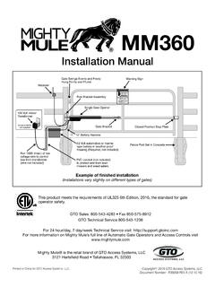
5 Intended for use in a commercial location or building such as a multi-family housing unit (five or more single family units) hotel, garages, retail store or other building servicing the general access vehicular gate Operator Class III A vehicular gate Operator (or system) intended for use in a industrial location or building such as a factory or loading dock area or other locations not intended to service the general access vehicular gate Operator Class IV A vehicular gate Operator (or system) intended for use in a guarded industrial location or building such as an airport security area or other restricted access locations not servicing the general public, in which unauthorized access is prevented via supervision by security IClass IIClass IIIC lass IVIncorrect Installationusing a Catch Post! Correct Installation with Catch RollersWallCatch RollersGate1/2" ClearanceBetween Gateand RollersMinimum Clearance of 5" Between Back of gate and Wall or Other Objects in gate 's Path1/4" Clearance from Top of GateFor safety reasons, a physical stop MUST be installed on the gate prior to Installation of the gate Operator .
6 This will assure that the gate does not exceed movement limits and derail while in in Fully Opened PositionGate ClearancesIMPORTANT! Because gate coasting distance varies with temperature, Elite DOES NOT recommend the Installation of a catch post. This could cause the gate to collide with the Rollers(Elite Part # A UHM)IMPORTANT NOTICE! Installers are required to adhere to this procedure: The UL required Warning Signs must be installed in plain view and on both sides of each gate installed. Each sign is made with fastening holes in each corner and should be permanently secured in a suitable manner. Also the warning sticker should be placed on the Operator so it is clearly Sign Clearly Visible on gate OperatorWarning Signs on Both Sides of GateOwners Must Never Let Pedestrians Cross the Path of a Moving gate !Owners Must Never Mount Any gate Operating Devices Accessible In Between the gate and the Wall!
7 Owners Must Never Mount Any gate Operating Devices Accessible Through the gate !CAUTIONCAUTIONCAUTIONW arning Signs on Both Sides of GateOver-Travel Stopson Both Ends ofGate RailGuide RollersGuide Rollers2"x 2" Mesh Wire Across Entire GateWarning Sign Clearly Visible on gate OperatorReinforced Concrete to Bolt Operator on115 VAC for Each gate Listed Underground Conduit for WiresPedestrians MUST have a Separate Walkway!3" Maximum Picket WidthSteel V-Groove, High Speed Ball Bearing WheelsBe sure to read and follow all Elite and UL Instructions before installing and operating any Elite products. Elite Access Systems, Inc. is not responsible for improper installations or failure to comply with local building hp Motors, 120 VAC, gate Length 37 feetMaximum gate Weight 800 hp Motors, 120 VAC, gate Length 37 feetMaximum gate Weight 2000 hp Motor, 120 VAC, 4 amp.
8 Maximum gate Length 37 feet Maximum gate Weight 1000 StopOver-Travel StopFRONT INSTALLATIONR eason: Cost effecientREAR INSTALLATIONR eason: Chain is not visibleCEILING MOUNT UNDERGROUNDR eason: Space effecient/chain is not visibleIt is highly recommended installing over-travel stops at both ends of the gate rail in any type of Installation , to prevent StopOver-Travel StopIdler Wheel must have Safety CoverFRONT INSTALLATIONREAR Installation COVER "2"Cut the chain access slot on the one side of the cover to the exact : For safe operation of the gate opener do not cut the slots any wider or longer than shown. DO NOT modify the housing in any way other than front bracket with gate in open rear bracket with gate in closed the cover 17 1/2 inches sure the idler wheel has a safety INSTALLATIONCONCRETE PAD AND gate ATTACHMENT6"Concrete (Reinforced Recommended)Above GroundBelow Ground24"24"24"Rear InstallationFront InstallationOver-TravelStops on BothEnds of RailCover over WheelOver-TravelStops on Both Endsof Rail10"8"12"12"Red Head Fastener1/2" x 3 1/2"Suggested Installation for dirt ground.
9 The measurements depend on the type of ground (ie., asphalt, cement, dirt)Follow gate manufacturers specifications and local building codes for setting AND Operator DISTANCECHOOSING MOVEMENT ONEXITLOOPSAFETYLOOPCENTERLOOPGATELOCKED 60 POWEROVERLOADOFFW4 OPEN LEFTDC-BACKUPOPEN RIGHT3 SENSORSRESETMOTOR1313 ONGBMS LINKARADIOMER60 OFF13 ONOPEN LEFTOPEN ONEXITLOOPSAFETYLOOPCENTERLOOPGATELOCKED 60 POWEROVERLOADOFFW4 OPEN LEFTDC-BACKUPOPEN RIGHT3 SENSORSRESETMOTOR1313 ONGBMS LINKARADIOMER60 OFF13 ONOPEN LEFTOPEN RIGHTOpen to the LeftOpen to the RightOmni Control BoardOmni Control Board4"MinimumDistanceBetween gate and SprocketCorrect InstallationIncorrect InstallationPlateEach notch indicates an estimated 1 inch of gate travelNutPush the Power OFF!2. Push the plate inward. Roll the nut to the direction Place the plate back in the Turn the machine If you need more adjusting, repeat the Adjusting, Do the Following:HOW TO CONNECT POWERADJUSTING gate TRAVELING DISTANCEUse Listed Conduit for Supplying Power to the UnitSuggestion: Seal all open holes of electronic box with sealant when finished Not Use This Outlet Unless You Are An Authorized Service TechnicianGate Operator MUST be properly : ELITE ACCESS SYSTEMS, INC.
10 Is not responsible for conflicts between the information listed in the above chart and the requirements of your local building codes. The information is for suggested use only. Check your local codes before Wires(Neutral)Black Wires(120 VAC)Green Wires (Ground)16 Gauge150 Feet14 Gauge250 Feet12 Gauge400 Feet10 Gauge650 Feet8 Gauge1000 Feet4 Gauge2200 FeetWIRE GUAGE REQUIREMENT FOR 120 VAC POWER SUPPLY: 1/2 HP AND DUAL MOTOR ONLYM inimum:15-AmpBreaker Switch Per Operator RequiredADJUSTABLE TIMERDO NOT Touch Alarm SensorAdjusted by Qualified Service PersonnelThe level of sensitivity has to do with the weight of the gate and the condition of sensitive = if the gate stops or reverses by itself. Not sensitive enough = if the gate hits an object and does not stop or : If the power supply to the gate Operator is less than 99 volts, adjust the alarm by turning the alarm adjustment counter-clockwise enough to actuate the alarm when obstructed but not sensitive enough for false triggering to ONEXITLOOPSAFETYLOOPCENTERLOOPGATELOCKED 60 POWEROVERLOADOFFW4 OPEN LEFTDC-BACKUPOPEN RIGHT3 SENSORSRESETMOTOR1313 ONGBMS LINKA13 Maximum SensitivityMinimum ONEXITLOOPSAFETYLOOPCENTERLOOPGATELOCKED 60 POWEROVERLOADOFFW4 OPEN LEFTDC-BACKUPOPEN RIGHT3 SENSORSRESETMOTOR1313 ONGBMS LINKATIMER60 OFFOPEN LEFTOPEN RIGHT313 ONTimer ONTIMER60 OFFOPEN LEFTOPEN RIGHT313 ONTimer OFFSet Timer 1 to 60 secondsTimer can be set from 1 to 60 seconds ( Timer ON ), or for push open/push close type operation ( Timer OFF ).