Transcription of GRX-TVI Control Interface
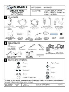
1 Espa olFran aisPortugu sDeutschItalianoNederlands and Operation Instructions Please Read Before Installing Occupant CopyGRX-TVI Control InterfacePhase Control to 0-10 V- 100-277 V~ 50 / 60 HzDescription The GRX-TVI provides 0-10 V- Control and ballast/driver switching capabilities in one enclosure. The GRX-TVI gives a 100-277 V~ dimmer the ability to Control current sourcing 0-10 V- ballasts or LED drivers (loads) powered by 100-277 V~. The dimmer can be forward phase,reverse phase, or center phase (for a sample of approved dimmers, see the list on spec sheet P/N 369247).
2 The GRX-TVI provides switching relays that can handle the in-rush current for a circuit of ballasts/drivers. The GRX-TVI can also be used to switch any of the load types listed Specifi cations Provides a IEC PELV/NECR Class 2 isolated 0-10 V- output signal that conforms to EN60929 and IEC60929; Accepts any phase Control signal;Accepts a constant-gate drive fl uorescent signal ( Control unit should be confi gured for fl uorescent load type) Input Power V~ 50/60 Hz H2/L2 20 mA Input Rating DH2/DL2 mA Input Rating 0-10 V- Output 10 A-300 mA - Sinks current only (maximum 150 ballasts/drivers) Terminals Two 12 to 20 AWG ( to mm2) conductors per terminal.
3 Mounting NEMA Type 1 enclosure, indoor use only. Environmental 32 to 104 F (0 to 40 C). Weight lb (2 kg) COOPERSBURG, PA 18036 Interface CONTROLC ontrol Input: 100-120V, 220-240V 50/60 HzSwitches: 100-277 VACGRX-TVI Source/Load Type230 V~ (CE)100-277 V~ (Non-CE)Fluorescent:Electronic Capacitive Non-DimOther Manufacturer s 0-10 V-Ballasts/drivers (0-10 V- source only)10 A10 A16 A16 ALED10 A16 AIncandescent10 A16 ALow-Voltage10 A16 AMetal Halide10 A16 ANeon/Cold Cathode10 A16 AMotors5 A @ 230 V~ CE1/2 HP @ 100 - 120V~11 2 HP @ 200 - 277 V~P/N 032443 Rev.
4 A Important installation Information Install in accordance with all national and local electrical codes. Check for short-circuited loads during new installations before wiring the GRX-TVI . WARNING - Shock Hazard. To avoid the risk of electric shock, locate and remove fuse or lock circuit breaker in the OFF position before proceeding. Wiring with the power ON could result in personal injury or death. Note: Multiple power feeds could be provided. Ensure that all feeds are off before wiring. Proper short circuit and overload protection must be provided at the distribution panel.
5 You can use up to a 20 A (16 A for CE) maximum circuit breaker/MCB or equivalent (tripping curve C according to IEC 898/EN60898 is recommended) with adequate short circuit breaking capacity for your installation . Terminal blocks are rated for two 12 to 20 AWG ( to mm2) wires per terminal. Strip 3/8 in (10 mm) of insulation from wires. Note: 277 V~ operation on the Control terminal was a design feature added September 2013. To check whether your TVI has this feature, please ensure the front label of the TVI shows the acceptable voltage range as 100 - 277 V~ for the Control input.
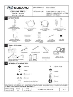
6 Prior revisions of the unit had (2) L2/H2 terminals (one for 120 V~ and one for 240 V~). The current design of the unit accepts a universal voltage (100 - 277 V~), so either of these terminals can be used for the Control feed. They are internally tied V- Ballast/driver0-10 V- Ballast/driver0-10 V- Control Fluorescent Zone/Load 10-10 V- Control Fluorescent Zone/Load 1 Switch Fluorescent Zone/Load 2 Incandescent Zone/Load 3 Control Unit / DimmerPower from Distribution PanelGRX-TVIGRX-TVIB allast/driverClass 2/PELV Accessory Controls3/8 in(10 mm) Note: When using a Control Unit, a GRX-TVI is required for each 0-10 V- fl uorescent zone.
7 (A 3-zone Control Unit with two fl uorescent zones and one incandescent zone is shown as an example.)System Wiring Layout Find a suitable location for mounting. Decide on the proper location for the GRX-TVI (NEMA Type 1 enclosure, indoor use only). The environment where the GRX-TVI is placed must have an ambient temperature range of 32 to 104 F (0 to 40 C). Mount the enclosure vertically on a wall (screws not provided). Mounting method must be able to support weight and forces applied during installation . Internal relays will click while in operation mount where audible noise is acceptable.
8 Warning - Shock Hazard. To avoid the risk of electric shock, locate and remove fuse or lock circuit breaker in the OFF position before proceeding. Wiring with the power ON could result in personal injury or - in. (6mm)Four ScrewsSecure in.(155 mm) in.(84 mm) in.(318 mm) in.(298 mm) in.(102 mm)Mounting DiagramFour Mounting Holes Diameter: in (6 mm)Four Screws Secure in(298 mm) in(318 mm) in(102 mm) in(155 mm) in(84 mm)WALLN2DL2/DH2L1/H1 100-277 V~N1SL1/SH10-10 Volt-L2/H2100-277 V~Wiring1. Turn power off at fuse box or circuit breaker Note: Multiple power feeds could be provided.
9 Ensure that all feeds are off before Wire Control per appropriate wiring diagram (see next page) using wire connectors provided. Dots on diagrams represent wire connectors. Wiring Diagram A shows a GRX-TVI wired from one distribution panel. If the power requirement of the complete system is less than an MCB/circuit breaker rating and L1/H1 and L2/H2 are both coming from the same phase, one feed can be jumpered inside the enclosure (as shown on Page 3). Wiring Diagram B shows a GRX-TVI wired from two separate distribution panels that may be different phases or voltages.
10 Use the internal terminal block label to see where to land wires. - The label shows two separate Line/Hot terminals (L1/H1 & L2/H2). L1/H1 is the Line/Hot feed to power the lighting load. L2/H2 is the Line/Hot feed that powers internal circuitry of theGRX-TVI. Note 1: Not all terminal blocks are required to have a connection for proper operation. Note 2: The power feed to the Control Unit (DL2/DH2) and L2/H2 of the GRX-TVI must be the same phase! Class 2/PELV, 0-10 V- wiring from a ballast/driver to the GRX-TVI must be separated from the power wiring.