Transcription of Installation Manual for AltAlert 3070G Icarus Instruments ...
1 Installation Manual for AltAlert 3070G Icarus Instruments , Inc. 7000 Carroll Ave. Ste 200 Takoma Park, MD 20912 301 891 0600 301 891 0666 fax email: February 1999 Revision AltAlert 3070G Installation Manual Introduction The AltAlert 3070G must be installed by an FAA approved avionics facility. The basic connections involve the altitude encoder code lines and an audio output. The optional GPS annunciators and CDI switching signal, if used, require connection to the GPS receiver and CDI switching relay box. The 3070G also optionally provides Mode C altitude data in a serial format for most GPS receivers. This eliminates the need to wire all of the Mode C code lines to both the AltAlert 3070G and the GPS receiver.
2 The 3070G GPS option provides the four annunciators, serial altitude data, and the CDI switching signal to an external relay that is NOT provided. FAA Advisory circulars and 2A apply to AltAlert concerning Installation practices. The AltAlert is totally passive and non-intrusive and is completely isolated from the encoder signals with 100K series resistors on all code lines. No failure of AltAlert can have any affect upon the integrity of the encoder code lines. AltAlert 3070G weighs under a pound and has therefore very little effect upon weight and balance. The power requirements are approximately 100 ma at any voltage from 10 to 30 volts. The power must be protected with a fuse or circuit breaker.
3 The 3070G should be connected to the avionics power bus. AltAlert 3070G consists of a single module that will mount in a standard 2 1/4 instrument cutout. The 3070G contains a time-of-day clock powered by an internal lithium battery. The existing aircraft clock may be replaced with the 3070G . The 3070G also has an internal approach timer and fuel timer. AltAlert is compatible with all modern encoder/transponder combinations that do not require a pulsed strobe line. As long as the encoder outputs are valid at all times (except warm up), the AltAlert will function properly. If the transponder is a Narco AT-50 or AT-50A, please consult the factory for special procedures.
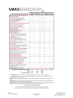
4 The 3070G has been successfully tested on all modern transponders that do not use a pulsed strobe line. The 3070G has an STC number SA1379GL. A PMA has been issued for the 3070G . Harness fabrication The supplied interconnection diagram (Table 1) details the wiring between the 3070G and the existing encoder/transponder and the audio system. The D4 encoder code line (J1/pin 1) is optional and is required only if the encoder can exceed 30,700 feet. The DC input power must be protected with a fuse or circuit breaker. The installer must perform a DC load analysis to determine that the addition of the AltAlert will not overload the power available.
5 Only 100 ma is required for the entire unit. The AltAlert Mode C code line inputs must parallel the existing encoder code line outputs. There is an internal 100K series resistor connected to each encoder input signal to insure complete isolation. The 6200 model will function to 62,700 feet. The D4 line does not have to be connected if the encoder does not have this bit active. One ground signal must connect the AltAlert to the encoder ground. Both the encoder and AltAlert require a pullup voltage supplied by the transponder. The transponder must be on for the altitude functions of the AltAlert to function, otherwise an Eerr (encoder error) will display.
6 The audio output is designed to drive a 500 ohm load with 140 mw available in the loudest position. The loudness can be adjusted in the AUX mode. The audio output should go to an unswitched input on the audio panel if available. The audio output can drive the headphone bus directly although a small series isolation resistor (100 to 470 ohms) may be necessary if the audio is too loud at the lowest setting. Note that there is a separate audio return line (J1/pin 14) that must go to the audio panel's ground. This is a transformer coupled output and this ground return must be used. (The original 3070 did not require this ground to pin 14) There is a separate output for a Sonalert that can be used if there are no audio inputs available on the audio panel.
7 However, there are certain stepped audio tones that are just beeps if the Sonalert is used. It is strongly recommended that the audio output be used instead the Sonalert since many pilots use headphones and the Sonalert tone can be easily lost or confused with other Sonalerts in the aircraft. GPS Signal Connections (Optional) on J2 The GPS connections are shown in Table 2. Note that the 3070G provides Mode C altitude data in a serial format compatible with all Trimble, Garmin, Northstar, and Apollo GPS receivers. If the 3070G is used to provide serial altitude information to the GPS, there is no need to connect the Mode C code lines to the GPS receiver.
8 Annunciators connections The AltAlert has four bright deadfront GPS annunciators labelled MSG, APR, HLD, and WPT. These are wired to the appropriate annunciator outputs on a GPS receiver that has a Message output, Approach output, Hold output, and Waypoint output. The Trimble IFR approved GPS receivers have all these four signals available. Other GPS receivers may not have all of these particular outputs. The internal annunciator lamps are all 28 volt, but 14 volt units are available on special order. Note that pin 13 of J2, the GPS connector is the power source for the GPS annunciators. We recommend that this pin be wired to the arm of a small SPDT switch that has aircraft bus voltage on one side and the dimmer bus on the other side.
9 This day/night switch allows the four annunciators to be dimmed in flight in the night position while providing full intensity in the day position. All GPS receivers have the Waypoint output and some also have one or more of the other annunciator outputs available. The 3070G has the ability to give an alphanumeric alert on the display as well through the audio system when any combination of the four annunciator signals come on. For example, it s important for the pilot to be aware of a waypoint passage when flying an IFR approach. The annunciator lamp combined with the flashing WPT alert and audible alert (beeps) assures that the pilot will not miss the GPS annunciation.
10 To select which of the four annunciator signals will generate a GPS alert with accompanying audio output, see the Special Parameter section at the end of this document. CDI switching signal and GPS/NAV annunciators The 3070G has a pilot switchable output that will drive a CDI relay box such as the NAT RS08 series or equivalent. The CDI mode on the 3070G will toggle the CDI switching signal and cause the CDI relay box to switch the CDI source. The CDI output on the 3070G is a high current open collector transistor. The CDI relay box drives two annunciator lamps located on the lower left of the 3070G labelled GPS and NAV. These annunciators show the pilot which nav source is currently selected.