Transcription of INSTALLATION / OPERATING INSTRUCTIONS …
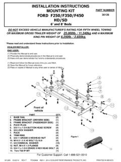
1 30144N-01/09/15 REV GPCN4742 2011, 2014 CEQUENT PERFORMANCE PRODUCTS, INC PRINTED IN MEXICOFor Kit 30144 For INSTALLATION Assistance or Technical Help, Call 1-800-632-3290 DEALER/INSTALLER:(1) Provide this Manual to end user.(2) Physically demonstrate hitching and unhitchingprocedures in this Manual to end user.(3) Have end user demonstrate that he/sheunderstands USER:(1) Read and follow this Manual every time you use hitch. (2) Save this Manual and Hitch Warning Hang Tag for future reference.(3) Pass on copies of Manual and Hitch Warning Hang Tag to any otheruser or owner of hitch. (4) Never remove hitch warning decals as shown Figure 33 of this manual. If damaged, contact Cequent Performance Products, Inc.(1-800-632-3290) for free Pin ZerkHitch HandleSlider HandleJaw To HoldKing PinSkid PlateFigure 1 INSTALLATION / OPERATING INSTRUCTIONSR eese Elite SeriesFIFTH WHEEL SLIDER HITCH30144N-01/09/15 REV GPCN4742 2011, 2014 CEQUENT PERFORMANCE PRODUCTS, INC PRINTED IN MEXICOFor Kit 301441.
2 GUIDELINES FOR MATCHING TOW VEHICLE AND TRAILERP. 2-42. PLASTIC BED LINER INSTRUCTIONSP. 53. CENTER SECTION HEIGHT ADJUSTMENTP. 64. OPERATING HANDLE INSTALLATION INSTRUCTIONSP. 74. INSTALLATION AND REMOVAL OF HITCHP. 8-95. OPERATING INSTRUCTIONSP. 10-166. MAINTENANCEP. 17-187. PARTS LISTP. 198. LIMITED LIFETIME WARRANTYP. 201. Check Tow Ratings:Vehicle Tow Series Hitch Rating:_____ Trailer Weight (Fig. 2):_____.*Trailer weight should be the lowest of these recorded ratings for safe towing Cequent Performance Products, Inc. hitches are designed for use with recreational fifth wheel trailers only. Hitch applications other than recreational fifth wheel trailers must be approved in writing by Cequent Performance Products, Inc. Engineering Department. 3. Use only a SAE 2-inch king pin with your Elite Series Fifth Wheel Approximately 15%-25% of trailer weight should be on hitch (Pin Weight). See Fig. TRAILER + FULL WATER TANKS + CARGO, GROSS TRAILER WEIGHTFig.
3 215-25%GROSS TRAILERWEIGHT(PIN WEIGHT)75-85%GROSS TRAILER WEIGHTF igure 3 GUIDELINES FOR MATCHING HITCH TRUCK AND TRAILERWARNING:Failure to follow all of these INSTRUCTIONS may result in death or serious injury!INDEXWARNING:Failure to check and follow tow ratings could result in tow vehicle damage or truck and trailer separation while hauling. Trailer and its contents together must not exceed truck, hitch and/or trailer tow ratings. Towing vehicle must have a manufacturer s rated towing capacity equal to or greater than the gross trailer weight (dry weight of the trailer plus payload of the trailer). (See Fig. 2) Gross weight of trailer must not exceed 18,000 pounds. King pin weight must not exceed 4,000 pounds. (See Fig. 3). If in doubt have king pin weight measured by qualified REV GPCN4742 2011, 2014 CEQUENT PERFORMANCE PRODUCTS, INC PRINTED IN MEXICOFor Kit 301445. Trucks come in many different configurations. Cequent Performance Products, Inc hitches are designed for use in light trucks such as the Ford F-Series, the Chevy Silverado and the Dodge Ram.
4 Cequent Performance Products Inc. recommends the use of long bed (8ft) light trucks for the best combination in truck - trailer turning clearance. 6. If a short bed pickup (less than 8 ft. but longer than 6 ft.) is to be used for towing, Cequent Performance Products , the trailer be equipped with a minimum 13 extended pin box to help gain additional truck -trailer turning clearance (See trailer manufacturer for options) (See Fig. 5). 7. The height of the hitch and the pin box should be adjusted so the trailer is approximately level as it is towed. Allowapproximately 6 inches clearance between the top of the pickup walls and the underside of the front of the trailer for pitch and roll of the trailer. (See Fig. 6). Allow more clearance between pickup walls and trailer for off road 4 Conventional Pin BoxExtended Pin BoxFigure 5 Rule of thumb:The distance from the back of the truck cab to the center of the rear truck axle ( X in Fig. 4), should be approximately 4 inches greater than one-half the trailer width ( Y in )WARNING:Do Not install this fifth wheel hitch on or attempt to tow with a short bed pickup truck that has a bed shorter than 6 ft.
5 !Approximately 6 InchesLevel TrailerFigure 6 CAUTION:The measurements above are your measurements are close to these numbers re-checkclearances. If vehicle and/or trailer has any added bed vicinity accessories ( fairings, air dams, ground effects,bed rails, etc.). Additional dimensioning and clearance checks have to be PinRV TrailerTruck330144N-01/09/15 REV GPCN4742 2011, 2014 CEQUENT PERFORMANCE PRODUCTS, INC PRINTED IN MEXICOFor Kit 301448. Hitch height determination:With trailer leveled and on level ground measure from the ground to the king pin box, Dimension A in Fig. 7. Secondly, measure from the height of the inside of the truck bed to the ground, Dimension B in Fig. 7. Dimensions C and D in Fig. 7 can be used to determine the amount of clearance over the side rails, as mentioned in instruction #7 (Additional clearance may be needed for off road maneuvering and/or steep inclines while turning).Hitch Height = A B + 2 The 2 value is an estimate of suspension compression due to king pin weight of the trailer.
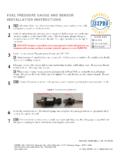
6 This compression could range between 1 -5 depending on the truck being used and the trailer being C + 2 > 6 as noted in instruction # *MEASURED WITH TRAILER LEVEL,ON LEVEL GROUNDWARNING: Connection for trailer wiring must be located at the side of the truck bed between the driver s seat and the rear wheel to prevent operators from working between the truck and trailer. Avoid putting any part of your body under the trailer or between the truck and trailer. Unexpected or accidental movement of the truck or the trailer can cause serious injury or death If you must place any part of your body under the trailer or between the truck and trailer you MUST perform ALL of the following steps: Check that the truck transmission is in park Check that the emergency brake is on Block in front of and behind all trailer tires Check that the trailer landing gear are resting on firm a lube plate is to be used with a Elite Series Fifth Wheel it must be at least 12 in diameter.
7 Cequent Performance Products , Inc. offers this optional lube plate as part # 83001 Figure 7430144N-01/09/15 REV GPCN4742 2011, 2014 CEQUENT PERFORMANCE PRODUCTS, INC PRINTED IN MEXICOFor Kit 30144 Plastic Bed Liner INSTRUCTIONS :If your truck is equipped with a plastic bed liner, then cutting or removal of the plastic bed liner MAY be necessary for the proper INSTALLATION and operation of the Elite Series FIFTH WHEEL SLIDER HITCH. Refer to the Plastic Bed Liner INSTRUCTIONS portion on this page for complete INSTRUCTIONS on where to cut your plastic bed liner if required. If your truck is notequipped with a plastic bed liner or if it has a spray in bed liner, than you should use the INSTRUCTIONS provided in the mounting kit for your specific truck and skip to page 6 for the rest of the Elite Series FIFTH WHEEL SLIDER HITCH the mounting kit INSTRUCTIONS for your specific and mark the distances provided in Figure 8 for the correct areas to be cut out of your plastic bed the plastic bed liner from your truck and cut out the marked areas with a saw or cutting device of your the plastic bed the rest of the Elite Series FIFTH WHEEL SLIDER HITCH 8 Front of Truck530144N-01/09/15 REV GPCN4742 2011, 2014 CEQUENT PERFORMANCE PRODUCTS, INC PRINTED IN MEXICOFor Kit 30144 TOOLS15/16" Socket & Open End Wrench Safety Glasses 200 ft-lb Torque Wrench White Lithium Grease & Wheel Grease3/4 & 1-1/2 Box or End Wrenches 9/16 Socket or Open End Wrench 3/4 Socket7/16 Socket or Open End WrenchTape Measure1.
8 Check all the boxes for all the components listed in Figure 1 and become familiar with component Loosely assemble the two slider assemblies to the center section using 5/8-11 bolts and lock washers NOTE A: Hole positions used in assembly will need to be made based on the head height measurements taken previously, calculated height closest to one of the following height dimensions: (2ndholes down), (3rdholes down), (bottom holes). DO NOT USE THE TOP HOLE. See Figure B: The ears on the center section should be offset forward, if clearances allow. See Figure 10. See mounting rail INSTALLATION INSTRUCTIONS for your specific 5/8 bolts in the center section to 170 ft-lbs. Center SectionEarsHitch HeightDO NOT Slider AssembliesFigure 9 Front of TruckFORWARD OFFSETREARWARD OFFSETF igure 10 CENTER SECTION HEIGHT AND ORIENTATION ADJUSTMENT 630144N-01/09/15 REV GPCN4742 2011, 2014 CEQUENT PERFORMANCE PRODUCTS, INC PRINTED IN MEXICOFor Kit 30144 Assemble the slider handle and the connector tube, minus the cotter pins.
9 The cotter pin holes should all be on the same sides. See Figure 11a. Make sure the lock cams inside the slider assemblies are orientated in the same direction, towards the front of the truck. See Figure 11b. If not, pull up on the jaw mechanism and rotate them until they do. Slide the slider handle assembly through the driver s side slider assembly. The slider handle must be in the same orientation as the lock cams in the slider assembly (handle points towards front of truck). See Figure 11b & 11c. Insert the cotter pins into the slider handle assembly (cotter pins should go into the holes that are nearest the slider assemblies). See Figure 11d. The indents on both slider assemblies must be aligned to each other and also aligned to the holes in the slider handle and connector tube. See Figure 11d. Do not put slider handle grip on slider handle yet. Figure 11dDriver s Side Slider Assembly cut away viewPassenger Side Slider Assembly cut away viewLock CamMust point towards front of truckLock CamMust point towardsfront of truckSlider Assembly HandleCotter Pin Holes Jaw Mechanism Jaw MechanismFigure 11aFigure 11bCotter pinsFRONT OF TRUCKFRONT OF TRUCKF igure 11cFRONT OF TRUCKS lider Handle AssemblySlider OPERATING Handle Installation730144N-01/09/15 REV GPCN4742 2011, 2014 CEQUENT PERFORMANCE PRODUCTS, INC PRINTED IN MEXICOFor Kit 30144 SLIDER HITCH REMOVAL:SLIDER HITCH INSTALLATION :Figure 12: Puck PlugsTruck BedPuck PlugPuckFigure 13:Front of TruckAnchor handle in Unlocked PositionElite Series Slider hitchPuckTruck BedBase Rail Assembly1.
10 Remove puck plugs from all (4) of the pucks in the truck bed (Figure 12) and store for use when hitch is Set Elite Series Slider hitch onto the pucks, and rotate handles into unlocked position(approximately perpendicular with base rail assembly (Figure 13) until hitch drops into pucks on all (4) Rotate (4) anchor handles into the locked position(anchor handles parallel with base rail assembly). Figure If system has any vertical movement, remove the slider from the hitch from the pucks. Remove the 3/16 cotter pin, turn the tee pin turn clockwise to tighten or turn counterclockwise to loosen (due this to all 4 mounting points). Replace cotter pin in the system (DO NOT BEND). Figure 15 and Repeat steps #2 and #3. Check the hitch for any vertical movement. 6. If the anchor handles lock into place and there is no vertical movement - pry open the ends of the 3/16 cotter pin and bend them back on themselves to secure. See figures 15 and 16.)