Transcription of installation, operation & Maintenance manual - …
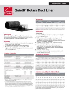
1 Floor-mounted Induction unitsacb 30/35installation, operation & Maintenance on innovationacb 30 & 35 Active Chilled Beam Models ACB30 & ACB35 are designed for installation in the ceiling space with down air discharge through separate ceiling-mounted grilles. The induced room air is drawn from the return air ceiling constructionEach concealed ceiling plenum-mounted active chilled beam unit consists of: Primary air plenum with primary air nozzles Round or Oval primary air inlet connection (1) (See Handings Configuration Key for available sizes) Supply air discharge slot (2) Condensate tray (3) Secondary water coil (4) 2 mounting brackets with 2 mounting holes each (5) Mixing chamber 2 or 4-pipe secondary water coil connection (6) (Connection can be configured as supply or re-turn based on on-site pipework) An identification label and commissioning chartNOTE: The separate supply and return air grille is normally provided by.
2 The location of the air and coil connections on each beam is determined by on-site personnel using the Handings Configuration Key on pages 7 & 8 and returning a filled out Unit Configuration schedule provided in the submittal installer is to provide the following: Required secondary water piping and valves including isolation valves, balancing valves, flow control zone valves and other valves/controls as specified. Primary air volume control balancing damper. Low resistance supply and return air grilles. Condensate drainage from the unit drain pan if specified. (Unit supplied with removable capped drain connection) All mounting hardware (threaded rods, nuts, etc.) and primary air flexible ducting.
3 If the supply air slot is more than 1/4 away from the grille, an in-fill piece between the unit and the supply air grille s frame is required to provide a seal between the unit and the grille. If the units drain pan is to be piped to drain, the in-fill piece will raise the unit above the grille frame to allow a fall in the drain line to provide gravity draining. Any other items necessary to complete the : Dadanco provides several accessories to complement your installation. Please reference the Accessories brochure or contact Dadanco for available ation1If units are not being installed immediately store in a well protected, dry, temperate location until they are ready for installation.
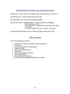
4 Reference the beams drawing for the weight at each designed length. Please follow your on-site safety standards when lifting units and utilize caution when inserting the beams into the ceiling. When possible please use a cart to transport the beams. Remember to wear proper personal protection constructionacb35acb30 SCHW HHW HHW SCHW 1 3 4 2 5 6 SCHW HHW HHW SCHW 5 1 2 3 4 6 ation Check the unit labeling to ensure that the proper unit is being installed at each location (pictured). Determine the orientation of the air and water connections in relation to the site plan. Check to ensure adequate clearance for the piping and duct connections. Check that the available ceiling space for the installation of the unit is free of other services and structural members.
5 Determine the position of the unit in the ceiling grid. NOTE: The unit can be positioned with the water coil facing toward the perimeter or interior of the conditioned space. When access is restricted near the perimeter, the unit should be installed with the coil facing the interior for improved service access. NOTE: Beams are designed to have (1) mounting bracket on each end of the unit with (2) mounting holes each. Ensure that each mounting bracket and mounting hole are utilized during wire hanging kits are available in the market with different fasteners and end fixings. The below instructions apply to the hanging kits available from Dadanco.
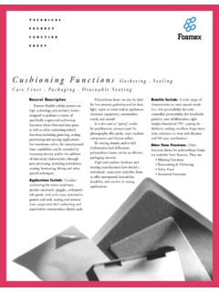
6 If other kits are used, please refer to the manufacturer s installation instructions. Attach a trapeze fastener to each mounting bracket on the ACB unit with the plastic clips provided in each kit. Secure each end fixing (stud or hanging loop) to the building structure. Pass each cable through the trapeze fasteners, and adjust to the height to at least 2-3 above the grille position. Once the ceiling grille is installed per manufacturers installation instructions, the chilled beam can be lowered into position by adjusting the cable lengths to as close to the top of the supply grille as possible. If the gap between the unit and the grille is 1/4 or less, no physical connection is needed between the discharge slot and the grille.
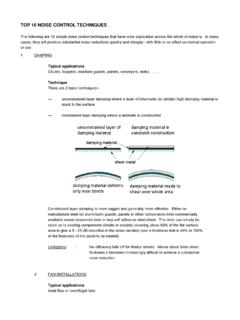
7 If the gap is greater than 1/4 , a sheet metal connection piece must be fabricated. Note: If drain pans are to be piped, connection pieces are typically needed to raise the unit high enough above the ceiling to allow for gravity hanging kit2 ACB45 ACB45 ACB55 Determine the position of the first under-slab Unistrut 2 foot channel bracket in the slab above or a ceiling structural member. The first Unistrut channel bracket should be positioned approximately the distance from the mounting brackets to the end of the unit and centered in relation to the width of the unit and its opening in the ceiling grid. Drill and secure the Unistrut channel bracket to the slab above or ceiling member with 3/8 bolts.
8 Install the second Unistrut channel bracket length at a position parallel to and at the correct distance from the first channel bracket along the length of the unit, according to the distance between brackets of the unit. Drill and secure the Unistrut channel bracket to the slab above or ceiling member with 3/8 bolts. Determine required length of 3/8 threaded rod between the Unistrut channel brackets and unit mounting brackets. Rod length should be approximately the distance from the suspended T-Bar ceiling tile frame lip to the underside of the slab above, or ceiling members, less the height of the brackets from the bottom of the unit.
9 This provides sufficient rod length to permit the unit to be raised and lowered without removing the hanging rods. Install (1) 3/8 flat washer, hex nut and Unistrut fixture nut to the top end of each 3/8 threaded rod. Install (1) 3/8 hex nut and flat washer to the other end of the threaded rod. Raise the unit into position above the ceiling grid frame, aligned to the ceiling grid opening. Install 3/8 flat washer and hex nut to the treaded rod at the underside of the unit mounting bracket to hold the rod loosely on the bracket. Do not fully tighten nuts at this time. Raise the position of the unit by tightening the lower hex nuts until the bottom lip of the unit is approximately 2-3 clear of the top of the suspended ceiling grid T-Bar frame.
10 Once the T-bar grid has been installed, lower the unit into the T-Bar frame by turning the bottom hex nuts. Unit supply/return air grille must fit completely into the T-Bar frame as if it were a ceiling : Unit can be moved front to back in the slots of the mounting brackets and left to right along the Unistrut channel bracket lengths to achieve proper alignment prior to tightening the fasteners. The unit must be supported from the ceiling slab/structural member. The unit weight should not be supported by the T-bar grid. Assure the unit is level and properly aligned in the T-Bar frame before tightening the mounting hardware. Tighten all 3/8 hex nuts once the unit is properly positioned and aligned in the T-Bar gridNOTE: The unit must be supported from the ceiling slab/structural member.