Transcription of Installation Practices
1 Section II Bare aluminum Wire and Cable Chapter 5 Installation Practices Once the route and length of a transmission or distribu tion line has been decided upon and the correct conductor size and type selected to carry the system load safely and economically, there are still several mechanical considera tions which will have an effect on Installation Practices and may influence the final choice of conductor. Line Design Factors The line designer must consider such factors as tower and pole locations and heights, span lengths, conductor tension and sags, ground clearances, etc. Technically, this means that he must have detailed knowledge of conductor sag-tension characteristics as a function of span length, temperature, and weight loading.
2 Much of this informa tion is supplied by wire and cable manufacturers in the form of tables and graphs that are to be used by the line designer.' Supplementing these, the line designer prepares other graphs, tables, templates, etc., that are related to a specific Installation . Thus, there are two distinct types of study: (1) That which is ordinarily performed by the engineers of the wire and cable manufacturers, and (2) that which is performed by the line-design engineer to utilize the manufacturer supplied information to best advantage. Users of this handbook probably are more likely to work with manu facturer-supplied graphs and data for application to a specific Installation than to work on the analysis of physical properties of conductors.
3 Hence the first section of this chapter endeavors to show how the line designer uses manufacturer-supplied data. This will be followed by a brief outline of the work ordinarily done under manu facturer's auspices. First. a few general statements that apply to both kinds of analysis are made. The "tcnsion limits" used as the basis fot calculations in thi~ chapter are s(a:ed a" nOt exceeding a speciried percentage or the rated of the cOnduCiQr. and these strengths are calculated in accordance with current AST~ standards. *If not otherwise Identified. charts and graphs in thiS chapter werc supplied by conductor manufacturers. An overhead conductor suspended between insulator supports aSsumes the shape of a catenary Curve provided the conductor is of uniform weight per ft.)
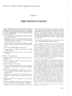
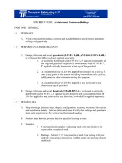
4 Usually it is convenient, without significant error, to regard the curve as a parabola.* A family of such curves exists for a given conductor and span, Fig. 5-1. The mid-point sag depends on tension in the conductor; the greater the tension the less the sag. To distinguish between span length and con ductor length. the latter is usually designated arc length. Anything that increases arc length after initial stringing increases the sag. Factors that may bring this about are ( J) thermal expansion of the conductor because of in crease of temperature above that during stringing, (2) in crease of conductor apparent weight because of wind and! or ice load, (3) creep gradually lengthening the conductor wires as a result of tension being applied over a period of many years, (4) stressing of wires beyond their elastic limits.
5 K-------S-SPAN SAG=D ~ L=~ of conductor ~ CLEARANCE t length Fig. 5-1. Diagram showing family of sag curves. The sag is less wi:h increase of conductor tension. * For sags up to 6% of span. the error is about In %, and for a sag of 10% of span, the parabola results in a sag about 2% too small. 5-1 bore aluminum wire and coble Though it might appear that sag-tension problems re lating to these subjects could be solved in a simple man ner, there are interrelated factors that must be taken into account. For example, ACSR has components that have differing stress strain characteristics, differing coefficients of thermal expansion, and they normally undergo differing unit tensile stresses.
6 Thus, it is evident that proper selection of span length and sags for a given profile and conductor in order to minimize Installation and operational costs requires a high order of engineering skill. However, for many applica. tions, the required sag tension analysis has been made by others. and the results are available in tables and graphs supplied by wire and cable manufacturers for all com mercially offered conductors. Only a moderate amount of additional work is necessary to utilize them for specific applications. Inilial and Final Sag Tension Charts Jor Variable Length Spans Two typical sag-tension charts are shown in Figs. 5 2 and 5 3. These charts apply to a 795 kcmi!
7 5417 ACSR Condor with standard class A steel core wire and include both bare and heavy loading as defined by the National Electric Safety Code (NESC) and listed in Table 5 1. The curves of these graphs show sags and tensions for various temperatures for spans from 400 to 1600 ft. Fig. 5-2 shows initial sags and tensions based on one-hour creep. Fig. 5 3 shows final sag and tension values. In this example, the sag after 10 year creep exceeds the final sag after heavy loading. Thus. creep is the governing condition in determining the final sag and tensions. Referring to the explanatory table accompanying Fig. 5 2. the sag tension values are shown for bare conductor (no ice or wind) at six different temperatures, 112 in.
8 Ice at 320 F and heavy loading of 112 in. ice plus 4 Ib/sq ft wind plus a constant. The resultant of the conductor weight plus ice and side wind load (which is at rigbt-angle to the line) is increased by a constant K = Ib per ft. [n the example, the cable weight alone is lb per ft. The resultant NESC Heavy loading on the conductor is Ib per ft. The upper set of curves of Fig. 5-2 shows conductor tension in Ib vs span in ft; the lower set shows sag in ft vs span in ft. The rated strengtb of this conductor is 28,200 lb. With full ice and wind load, the allowable tension as shown below the explanatory table is 40"70 of 28,200 or 11,280 lb. This value bas been selected as the maximum allowable tension and the No.]
9 I sag curve is drawn correspondingly. However, it should be noted that for spans below 721) ft, tbe tension as shown by cUrve 9 on the initial chart (Fig. 5-2) is less than 40 percent of In addition. several computer programs have been developed to do these calculations and they are available to utility and <:omputer engineers so they can do this work themselves. "If the conductor is. subject to electrical overloads, curves for the highest temperature likely to be encountered should be added.. the rated strength because, for spans shorter than this, the final tension limit of 25 percent of rated strength at OOF is ruling. This can be noted from curve 15 of the final chart (Fig.
10 5 3) where the tension levels out at 7,100 lb for these shorter spans and does not exceed 25 percent of rated strength. [n addition, the allowable initial tension on the unloaded or bare conductor, when installed, is percent or 9400 lbs. Since curve 15 on the initial chart does not exceed 9000 Ibs, this requirement is met. Since the probable average span for an overhead con ductor of this size is about 1000 ft, the strength margin for the conductor is even more favorable as seen by the reduced tensions above 720 ft. TABLE 5-1 National Electric Safety Code (1987 Edition) for Overhead Conductor-Mechanical Load Classifications Loading Description and Method of Obtaining Loaded District Weight per foot Light Cond.]