Transcription of Installation / Setup Guide - ThunderMax
1 #309-485 2004-2011 Dyna , 2010- 2013 XL Sportster , 2008-2010 Rocker , 2009 CVO FXSTSSE2 , 2008-12 XR1200 Seri al # TM RM All Models - Oxygen S ensor Ins tallati on Tips Your ThunderMax kit includes robust Wide-Band oxygen sensors that report data from every cylinde r combustion event to the ThunderMax ECM for automatic air/fuel corrections. These sensors replace the factory supplied narrow-band sensors first used on 2006 Dyna and in most cases are direct bolt-in replacements (2004- 2005 Dyna models will require the addition of 18mm sensor bungs to the exhaust header pipes). Installation of the wide band sensors into most bung-equipped headpipes presents no clearance problems; however, some pipe brands may require exhaust pipe modifica tio n or sensor bung relocation for interfe rence-free Installation .
2 The sensors must mount freely without contactin g surrounding components. If this is not possible, do not attempt to bend or modify the sensor in any way as it is a sensitive electronic component and will be damaged if you do so. Modify the pipe if required for clearance. Weld-in bungs are available for exhaust systems not equipped with bungs or if current bungs present clearance issues. Bungs should be located no more than 3-4 from the head/pipe connection (for ideal location, refer to the 2007 factory location). Weld-in bungs are available in st raigh t or angled style from many industry sources; see video Installation link on page 9.
3 Afte r Installation , route the sensor harness away from the engine and along the frame when possible , above the lowest frame point to avoid the possibility of dragging ground during operation. DISCLAIMER: NOT LEGAL FOR SALE OR USE IN CALIFORNIA ON ANY POLLUTION CONTROLLED MOTOR VEHICLES The user shall determine suitability of the product for his or her use. Installation and use on a pollution- controlled vehicle constitutes tampering under the EPA guidelines and can lead to substantial fines . Review your applic atio n and check your local laws before installing. Avoid routing harnesses where engine movement or sharp edges can contact and cut into the harnessesor connector the harnesses to the frame or existi ng component h arne sses , taki ng c are to avoid co ntac t wit h any vi brating component th at m ay chaff the sheathing or wires.
4 Some disassembly of bike components may be required for best harness routing. Remov e any prev iously ins talled ancil lary tuning de vi ce including oxy gen s ensor elimi nator s that may be plu gged int o the fact ory oxygen s ensor har nes s. All Models - A packet of dielectric g rease is includ ed wi th yo ur ThunderMax . Af ter y ou hav e installe d t he Pigtail communication cable harness, before ins talling the ECM connector, apply the provided dielectric gre as e to the inside lip of the ThunderMax ECM to ens ure t he rubber weather seal does not bi nd d uri ng Installation a nd acros s the clear case on the 36 pin ECM connector.
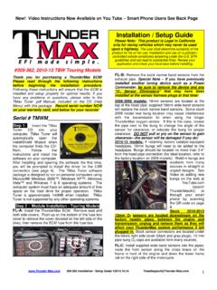
5 Sprea d t he grease across all of the female ter mina l openings, making su re th e grease penetrates openings. This grease will help maintain vital conductivity between the ThunderMax and the 36 pin connector. Also appl y d ielec tric gre as e to the ThunderMax oxygen sensor harness connector terminals for to help maintain conductivity, and to the outer housing to prevent binding upon Installation t o th e ECM. ww 309-485 Installation Guide ort@T om 1 The Model number on ECM will be 309-460 (the instructions and communication pigtail are the only difference).Thank you for purchasing a ThunderMax ECM! Please read through the following instructions before beginning the Installation procedure.
6 Following these instructions will ensure that the ECM is installed and Setup properly for optimal results. If you have any problems or questions, please refer to the TMax Manual. The manual can be found in the software (see part 2), under the Help button in the menu. Record serial number NOW, in the space below for later use registering your ECM. Part 1: Module Installation *CA Proposition 65 known to the state of CA to cause [cancer][birth defects or other reproductive harm] see for details Module Installat ion Sportster (Skip ahead for othe r mod els) Rem ove any previously inst alled an cill ary tun ing de vice including ox yg en se nsor elimi nators t hat ma y be plu gged into t he factory o xy ge n s ensor har ne ss.
7 XL-A Unpl ug and Remove the factory oxygen sensors. Rubber caps are included to cap off the factory oxygen harness connectors (see page 9).XL- B Remov e th e lef t si de cov er to expose the b attery and main fuse compartment. Remov e the mai n fuse cover, then the mai n fus e ( Note: if equipped with optional securi ty system, turn on ig niti on bef ore you remove the fuse to avoid tripping the alarm). XL-C: Remov e the sock et he ad screw a nd slide the EC M cov er tow ards the left side of the bike to remove it (remove wir es fr om ECM caddy cov er channels). XL-D: Remove the stock E CM o ut of the caddy, towards the primary side of the motorcycl e.
8 Lif t ta ng on the top of the cadd y to hel p release the unit. XL-E : Fu ll y depress connector tab and di sconnect the stock E CM fr om t he 36 pin connec tor. XL-F: Install ThunderMax Pigtail connector # 3 09- 424 to 36 pi n h arness connector pe r connector ins tructi ons. Run the communicatio n ca ble s traig ht up inside t he cadd y towards the left si de of the motorcycle, between the module area an d the frame bac k bone , comi ng out abov e the ba ttery . Us e a wir e tie on t he connector to t he mai n harness above the battery for easy access under left side cover. XL-G: Route the oxygen sensor harness into the ECM caddy.
9 Star ti ng from under the chassi s between the rear engine mount and rear frame cross member, behi nd th e belt , tigh t t o the engi ne cas e. Feed the ECM pl ug between t he bottom two oil tank hos es into the ECM caddy opening (it s a tight fit, you may have to push the plastic caddy forward whil e wor ki ng t he plug into the opening at t he caddy bottom). Pull the harness thr ough the caddy to the left side of the engine abov e th e pri mar y cov er, bei ng mindful t hat the rear oxygen sensor connector wil l limit how far the harness can pull up. XL-H: Insert the greased oxygen harness connector in to the ECM with the impri nted ThunderMax logo facing up.
10 U si ng a long Phillips screw driv er inserte d throu gh t he frame from right to lef t, tighten the (2) Philli ps connector screws. Con nec t t he greased 36-pin ECM connector to the ThunderMax ECM. Inst al l the ThunderMax ECM int o the ECM caddy while gently pulli ng t he oxygen sens or harnesses do wn from under the bike to reduce slack. Veri fy th at the h arnesses are clear of the dr ive belt. XL-I : Start ing from under the cha ssi s b et ween the re ar engine mou nt and rear fram e cros s member, fee d the oxygen sens or f or the ww tmaxsupp ort@T om 2 309-485 Installation Guide cylinder t ow ards the fron t of the engine between the left frame tube a nd the engine (a tight fit that may require some patience).