Transcription of Instruction Manual: Fisher D4 Control Valve …
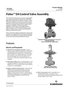
1 D4 Control Valve of Plug and Seat 1. Fisher D4 Control ValveW8531 IntroductionScope of ManualThis Instruction manual provides installation, maintenance, and parts information for the Fisher D4 Control not install, operate, or maintain a D4 Control Valve without being fully trained and qualified in Valve , actuator, andaccessory installation, operation, and maintenance. To avoid personal injury or property damage, it is important tocarefully read, understand, and follow all the contents of this manual , including all safety cautions and warnings. If youhave any questions about these instructions , contact your Emerson sales office or Local Business Partner D4 Control Valve is a compact, rugged Valve designed primarily for high pressure throttling applications.
2 This valveis ideal for use on pressure and flow Control applications within the oil and gas production industry. The D4 Valve alsomakes an excellent dump Valve for high pressure separators and D4 Control Valve meets the metallurgical requirements of NACE MR0175/ISO 15156 without environmental limitsfor temperatures below 135_C (275_F). If the temperature is above 135_C (275_F), the N07718 Belleville washers willimpose some limits, as shown in table ManualD103042X012D4 ValveJune 2017 Instruction ManualD103042X012D4 ValveJune 20172 Table 1. SpecificationsAvailable ConfigurationsSpring to CloseSpring to OpenValve Body Sizes and End Connection Styles(1)See table 2 Maximum Inlet Pressures and Temperatures(1)If the Valve nameplate shows an ASME pressure temperature class, maximum inlet pressureand temperature is consistent with the applicableclass per ASME If the nameplate does notshow an ASME class, it will show a maximum coldworking pressure at 38_C (100_F) (for example, 293bar [4250 psi])Maximum Pressure Drops(1)See tables 4, 5, 6, and 7 Input Signal to ActuatorSee tables 4, 5, 6, and 7 Actuator Maximum Casing Pressure(1) bar (50 psig)
3 Shutoff Classification per ANSI/FCI 70 2 and IEC 60534 4 Class IVMaterial Temperature Capabilities(1)Actuator Assembly: -40 to 93 C (-40 to 200 F) Valve Body Assembly:Standard Bonnet O Ring: -40 to 135 C (-40 to 275 F)Optional Fluorocarbon Bonnet O Ring: -23 to 204 C(-10 to 400 F)Flow CharacteristicEqual percentageFlow DirectionFlow up onlyPort DiametersSee table 2 Valve Plug Travel19 mm ( inch) Valve Plug StyleMicro Form Valve plugActuator Diaphragm Effective Area452 cm2 (69 inches2)Actuator Pressure Connection Size1/4 NPT internal1. The pressure or temperature limits in the referenced tables and any applicable ASME code limitations should not be 1 lists specifications for the D4 Control Valve .
4 Some of the specifications for a given Control Valve as it originallycomes from the factory are stamped on a nameplate located on the actuator spring ServicesFor information on available courses for Fisher D4 valves , as well as a variety of other products, contact:Emerson Automation SolutionsEducational Services - RegistrationPhone: 1-641-754-3771 or 1-800-338-8158E-mail: ManualD103042X012D4 ValveJune 20173 Table 2. Valve Sizes and Connection StylesVALVESIZE,NPSPORTDIAMETER,(INCHES) SCREWEDRAISED FACE (RF) FLANGEDRING TYPE JOINT(RTJ) FLANGED4250 psiCL150CL300CL600CL900 andCL1500CL600CL900 , , , , , , 1, = Available 3. D4 Environmental Limits for NACE MR0175/ISO 15156 with Sour TrimMAXIMUM TEMPERATUREMAXIMUM H2S PARTIAL PRESSURECOMPATIBLE WITHELEMENTAL SULFUR?
5 LimitYesTable 4. Maximum Shutoff Pressure Drops(1) for Fisher D4 Control valves (Spring to Close)When Used with Typical Control Instrumentation(2)INPUT SIGNAL TOACTUATOR0 to Bar(0 to 18 Psig)0 to Bar(0 to 20 Psig)0 to Bar(0 to 30 Psig)0 to Bar(0 to 33 Psig)0 to Bar(0 to 35 Psig)0 to Bar(0 to 50 Psig)SPRINGL ight RateHeavy RateINITIAL Bar( Psig) Bar( Psig) Bar( Psig) Bar( Psig) Bar( Psig) Bar( Psig)PORT DIAMETERM aximum Pressure (3)293(3)1918042254250(3)4250(3)27651160 610365293(3)293(3)1918042254250(3)4250(3 )276511606103652932932199249304250425031 8013407154302932932881236741425042504180 1785965590293293293143784842504250425020 8011307002932932931437848425042504250208 011307001.
6 The pressure or temperature limits in the referenced tables and any applicable ASME code limitations should not be For example, use the column marked 0 bar (0 20 psig) for a bar (3 15 psig) pneumatic controller with bar (20 psig) supply For applications with downstream pressure in excess of 196 bar (2845 psig), use 196 bar (2845 psig) for Maximum Shutoff 5. Maximum Shutoff Pressure Drops(1) for Fisher D4 Control valves (Spring to Close)When Used with Instrumentation with Restricted Output Range(2)INPUT SIGNAL to Bar(6 to 30 Psig) to Bar(2 to 33 Psig)SPRINGH eavy RateHeavy RateINITIAL Bar( Psig) Bar( Psig)PORT DIAMETERM aximum Pressure (3)210(3)1134523134250(3)3045(3)16356553 3018529329328212065394250425040951750945 5801.
7 The pressure or temperature limits in the referenced tables and any applicable ASME code limitations should not be For example, an Electro Pneumatic Transducer calibrated for bar (6 30 psig) output For applications with downstream pressure in excess of 118 bar (1715 psig), use 118 bar (1715 psig) for Maximum Shutoff ManualD103042X012D4 ValveJune 20174 Table 6. Maximum Shutoff Pressure Drops(1) for Fisher D4 Control valves (Spring to Open)When Used with Typical Control Instrumentation(2)INPUT SIGNAL TOACTUATOR0 to Bar(0 to 18 Psig)0 to Bar(0 to 20 Psig)0 to Bar(0 to 30 Psig)0 to Bar(0 to 33 Psig)0 to Bar(0 to 35 Psig)0 to Bar(0 to 50 Psig)SPRINGL ight RateHeavy RateINITIAL Bar( Psig) Bar( Psig) Bar( Psig) Bar( Psig) Bar( Psig) Bar( Psig)PORT DIAMETERM aximum Pressure (3)293(3)1877841244250(3)4250(3)27151135 600355293(3)293(3)2339953324250(3)4250(3 )
8 3380143076546529329329314780494250425042 5021301160715293293293178976042504250425 0257514108752932932931981096842504250425 0287515759852932932932931951234250425042 504250283017851. The pressure or temperature limits in the referenced tables and any applicable ASME code limitations should not be For example, use the column marked 0 bar (0 20 psig) for a bar (3 15 psig) pneumatic controller with bar (20 psig) supply For applications with downstream pressure in excess of 190 bar (2760 psig), use 190 bar (2760 psig) for Maximum Shutoff 7. Maximum Shutoff Pressure Drops(1) for Fisher D4 Control valves (Spring to Open)When Used with Instrumentation with Restricted Output Range(2)INPUT SIGNAL to Bar(6 to 30 Psig) to Bar(2 to 33 Psig)SPRINGH eavy RateHeavy RateINITIAL Bar( Psig) Bar( Psig)PORT DIAMETERM aximum Pressure (3)293(3)1968243264250(3)4250(3)28451195 6303802932932931568552425042504250226512 357651.
9 The pressure or temperature limits in the referenced tables and any applicable ASME code limitations should not be For example, an Electro Pneumatic Transducer calibrated for bar (6 30 psig) output For applications with downstream pressure in excess of 202 bar (2925 psig), use 202 bar (2925 psig) for Maximum Shutoff WARNINGA lways wear protective gloves, clothing, and eyewear when performing any installation operations to avoid avoid personal injury or property damage caused by bursting of pressure retaining parts or by uncontrolled processfluid, be certain the service conditions do not exceed the limits shown on the Valve nameplate and in tables 1, 4, 5, 6, and pressure relieving devices required by government or accepted industry codes and good engineering with your process or safety engineer for any additional measures that must be taken to protect against installing into an existing application.
10 Also refer to the WARNING at the beginning of the Maintenance section in thisinstruction ManualD103042X012D4 ValveJune 20175 WARNINGWhen ordered, the Valve configuration and construction materials were selected to meet particular pressure, temperature,pressure drop, and controlled fluid conditions. Responsibility for the safety of process media and compatibility of valvematerials with process media rests solely with the purchaser and end user. Since some body/trim material combinationsare limited in their pressure drop and temperature ranges, do not apply any other conditions to the Valve without firstcontacting your Emerson sales office or Local Business Partner.