Transcription of Instruction Manual: Fisher Vee-Ball V150 and V300 NPS 14 ...
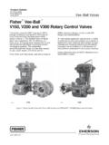
1 Vee-Ball V150 and v300 nps 14 through 24x20 Rotary control of Seal and Ball Open 1. Fisher Vee Ball ValveW6087 IntroductionScope of ManualThis Instruction manual provides installation, operation, maintenance, and parts ordering information for NPS 14, 16,20, and 24x20 V150 and NPS 14, 16, and 20 v300 rotary control valves . For smaller valves (NPS 1 through 12), refer tothe Vee Ball V150, V200 and v300 Rotary control valves NPS 1 through 12 Instruction manual (D101554X012). Forinformation on ENVIRO SEALt packing, see the ENVIRO SEAL Packing System for Rotary valves Instruction manual(D101643X012). Refer to separate manuals for information concerning the actuator, positioner, and not install, operate, or maintain V150 and v300 valves without being fully trained and qualified in valve, actuator,and accessory installation, operation, and maintenance. To avoid personal injury or property damage, it is importantto carefully read, understand, and follow all the contents of this manual, including all safety cautions and warnings.
2 Ifyou have any questions about these instructions, contact your Emerson sales office or Local Business Partner V150 or v300 Vee Ball valve with a V notch ball is used in throttling or on off service. The V150 valve (figure 1) is araised face flanged construction available in CL150. The v300 valve is a raised face flanged construction available inCL300. The splined valve shaft connects to a variety of rotary ManualD101957X012V150 and v300 ValvesJuly 2017 Instruction ManualD101957X012V150 and v300 ValvesJuly 20172 Table 1. SpecificationsValve Sizes and End Connection StylesV150: NPS 14, 16, 20, and 24x20 with CL150raised face flanges as shown in table 3V300: NPS 14, 16, and 20 with CL300 raised faceflanges as shown in table 3 Maximum Inlet Pressure(1)Consistent with applicable ASME or EN 12516-1 ratingsStandard Flow DirectionForward (into the convex sealing face of the ball)Actuator MountingJRight hand, or Jleft hand as viewed from theupstream end of the valve. Standard valveconstruction with standard ball rotation is withright hand mounting.
3 Optional valve constructionwith optional ball rotation for left hand mounting isavailable upon RotationStandard: Ball rotates Counterclockwise to Close(CCW) when viewed from actuator side of valveOptional: Ball rotates Clockwise to Close (CW)Maximum ball rotation is 90 degreesValve/Actuator ActionWith diaphragm or piston rotary actuator,field reversible between push down to close(extending actuator rod closes valve) andpush down to open (extending actuator rod opensvalve)1. The pressure/temperature limits in this manual and any applicable standard or code limitation for valve should not be 2. Valve Sizes, Drive Shaft Diameters, and Valve Assembly WeightsVALVE SIZEDRIVE SHAFT DIAMETERVALVE ASSEMBLY 3 1 x 1/8 x 1/252475511551661600(1)24x20(1) 1/2757- - -1666- - -1. NPS 24x20 available only for V150, not for v300 3. Valve Sizes, End Connection Styles, and Ratings(1)(2)VALVE BODYMATERIALFLANGE COMPATIBILITYRATINGFACE TO FACE DIMENSIONWCC or CG8 MCL150 (V150) raised faceASME CL150 NPS 14 and 16 valves : ASME ShortNPS 20 valves : 508 mm (20 inches)NPS 24x20 valves : 610 mm (24 inches)CL300 ( v300 ) raised faceASME CL300 NPS 14 valves : 381 mm (15 inches)NPS 16 valves : 406 mm (16 inches)NPS 20 valves : 508 mm (20 inches)1.
4 Do not exceed the material temperature capabilities or the pressure drop limitations shown in bulletin :Vee The pressure/temperature limits in this manual and any application code limitations, should not be for these valves are shown in table 1 and bulletin :Vee Ball Fisher Vee-Ball V150, V200, and v300 Rotary control valves (D101363X012). Instruction ManualD101957X012V150 and v300 ValvesJuly 20173 Educational ServicesFor information on available courses for Fisher V150 and v300 valves , as well as a variety of other products, contact:Emerson Automation SolutionsEducational Services - RegistrationPhone: 1-641-754-3771 or 1-800-338-8158E-mail: numbers are shown in figure 10, unless otherwise indicated. WARNINGA lways wear protective gloves, clothing, and eyewear when performing any maintenance operations to avoid injury or equipment damage caused by sudden release of pressure may result if the valve assembly is installedwhere service conditions could exceed either the valve body rating or the mating pipe flange joint rating.
5 To avoid suchinjury or damage, provide a relief valve for overpressure protection as required by government or accepted industry codesand good engineering with your process or safety engineer for any additional measures that must be taken to protect against ordered, the valve configuration and construction materials were selected to meet particular pressure, temperature,pressure drop and controlled fluid conditions. Responsibility for the safety of process media and compatibility of valvematerials with process media rests solely with the purchaser and end user. Since some valve body/trim materialcombinations are limited in their pressure drop and temperature ranges, do not apply any other conditions to the valvewithout first contacting your Emerson sales office or Local Business the valve with the drive shaft in the horizontal position as shown in figure 1. WARNINGDo not allow the valve to be installed in the pipeline with the drive shaft in the vertical position because of excessive wear tocomponent valve If the valve is to be stored before installation, protect the flange mating surfaces and keep the valve cavity dry andfree of foreign Install a three valve bypass around the control valve assembly if continuous operation will be necessary duringinspection and maintenance of the Mounting the Actuator: Instruction ManualD101957X012V150 and v300 ValvesJuly 20174a.
6 The valve is normally shipped as part of a control valve assembly, with the actuator mounted on the valve. Thefactory makes actuator/valve adjustments before the valve is If the valve and actuator have been purchased separately or if the actuator has been removed, mount theactuator according to the Actuator Mounting section of this Be certain the valve and adjacent pipelines are free of any foreign material that could damage the valve Be sure the mating line flanges are aligned. Provide standard flat sheet flange gaskets (or spiral wound gaskets withcompression controlling centering rings) that are compatible with the process to figure 2 for required clearance for valve installation and stud length. Lubricate the studs with Install the valve using studs and nuts to connect the valve flanges to the pipeline flanges. The seal protector ring(key 3) end of the valve requires longer line flange studs than standard (see figure 2).Table 4. Required Clearances for Installation of Fisher V150 and v300 ValvesVALVESIZE,NPSDIMENSIONABM(2) (Min.)
7 NCL150 ASME (Short)(1)CL300CL150 ASME (Short)(1)CL300CL150CL300mm141620(3)3814 06508381406508175178235(3)15215217819721 0222133133159178190203 Inch141620(3)24x20(3,4) - (3) - - -1. ASME (Short) applies to NPS 14 and 16 valves Inlet flange stud bolt length is longer than the standard length as specified in ASME NPS 20, CL150 valves do not comply with ASME (Short).4. Valve body mates with NPS 24 ASME CL150 flanges. Internal based on NPS 20 valve 2. Required Clearances for Installation of Fisher V150 and v300 ValvesMANB13B6967 BA6064 1Do not attempt to use standard length line flange studs for the seal protector end of the valve. Refer to figure 2 forlength of flange studs all remaining studs. Tighten the nuts in a criss cross sequence to ensure the flange gaskets are properly loaded. WARNINGThe valve drive shaft is not necessarily grounded to the pipeline when installed. Personal injury or property damage couldresult if the process fluid or the atmosphere around the valve is flammable, from an explosion caused by a discharge ofInstruction ManualD101957X012V150 and v300 ValvesJuly 20175static electricity from the valve components.
8 If the valve is installed in a hazardous area, electrically bond the drive shaft tothe PTFE packing is composed of a partially conductive carbon filled PTFE female adaptor with PTFE V ring graphite packing is composed of all conductive graphite ribbon packing rings. Alternate shaft to valve bodybonding is available for hazardous service areas where the standard packing is not sufficient to bond the shaft to the valve(see the following step and figure 4).7. For hazardous applications, attach the optional bonding strap assembly (key 131, figure 4) to the valve drive shaft(key 6) with the clamp (key 130, figure 4) and connect the other end of the bonding strap assembly to the valvebody with the cap screw (key 23).8. Connect pressure lines to the actuator as indicated in the actuator Instruction manual. When an auxiliary manualactuator is used with a power actuator, install a bypass valve on the power actuator (if one is not supplied) for useduring manual operation. WARNINGP ersonal injury could result from packing leakage.
9 Valve packing was tightened before shipment; however, the packingmight need some readjustment to meet specific service conditions. Check with your process or safety engineer for anyadditional measures that must be taken to protect against process the valve has ENVIRO SEAL live loaded packing installed, this initial re adjustment will probably not be to the ENVIRO SEAL Packing System for Rotary valves Instruction manual (D101643X012) for parts are subject to normal wear and must be inspected and/or replaced as necessary. The frequency ofinspection and replacement depends upon the severity of service conditions. WARNINGThe Vee ball closes with a cutting motion. To avoid personal injury, keep hands, tools, and other objects away from the ballwhile stroking the personal injury from sudden release of process pressure. Before performing any maintenance operations:D Do not remove the actuator from the valve while the valve is still Disconnect any operating lines providing air pressure, electric power, or a control signal to the actuator.
10 Make sure theactuator cannot suddenly open or close the Use bypass valves or completely shut off the process to isolate the valve from process pressure. Relieve process pressureon both sides of the valve. Drain the process media from both sides of the Vent the power actuator loading Use lock out procedures to be sure that the above measures stay in effect while you work on the Always wear protective gloves, clothing, and eyewear when performing any maintenance operations to avoid The valve packing area may contain process fluids that are pressurized, even when the valve has been removed from thepipeline. Process fluids may spray out under pressure when removing the packing hardware or packing Check with your process or safety engineer for any additional measures that must be taken to protect against ManualD101957X012V150 and v300 ValvesJuly 20176 Packing MaintenanceKey numbers are shown in figure 10, unless otherwise indicated. A detailed view of the packing is also shown in the valve is equipped with the ENVIRO SEAL Packing System, refer to the ENVIRO SEAL Packing System for RotaryValves Instruction manual (D101643X012).