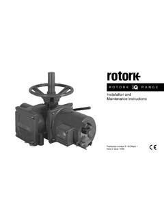
Transcription of Instruction manual for 'A' Range actuators
1 Syncropak 1400 seriesSyncropak 1600 seriesSyncrosetInstruction manual for'A' Range actuatorsPUB003-002 (E270E)Date of issue 01/16 This manual is produced toenable the user to install, operate,adjust, inspect and maintainRotork A Range valve the UK the electricalinstallation, maintenance and useof these actuators should conformto the requirements of theElectricity (Factories Act) SpecialRegulations 1908 and 1944 andthe guidance given in the 15thedition of the IEE WiringRegulations. The user shouldtherefore make himself familiarwith these regulations and otherStatutory Provisions relating tothe safe use of this the user should be fullyaware of his duties under theHealth and Safety at Work mechanical installationshould be carried out as outlinedin the manual and also inaccordance with the relevantBritish Standard Codes the actuator has nameplatesindicating that the actuator issuitable for installation inHazardous Gas Areas then thefollowing regulations apply.
2 Theelectrical installation,maintenance and use of theseactuators should be carried out inaccordance with BS 5345 Part 1:1976 and BS 5345 Part 3: inspection or repair should beundertaken unless it conforms tothe requirements given in thesestandards, and under nocircumstances should anymodification or alteration becarried out on the actuator as thiscould very well invalidate theconditions under which thecertificate was actuators are suitable foruse in Zone 1 and Zone 2explosive atmospheres only, andthey should not be installed inatmospheres where Group II Cgases are present.
3 Or wheregases are present with an ignitiontemperature less then suitability for lower ignitiontemperatures has been indicatedon the actuator nameplate. Anytest instruments applied to theactuator should be of to live electricalconductors of the actuator isforbidden in the hazardous areaunless this is done under aspecial permit to work asdescribed in Section 3 of themanual, otherwise all powershould be isolated and theactuator removed to a nonhazardous area for repair persons competent by virtueof their training and experienceshould be allowed to install,maintain and repair theseactuators, and they should carryout this work in accordance withthe instructions given in themanual.
4 The user and thosepersons working on thisequipment should be familiar withtheir responsibilities under theHealth and Safety at Work 1974 and relevant StatutoryProvisions relating to their installations outside the UKthe requirements of localregulations should be further information andguidance relating to the safeinstallation, maintenance and useof the Rotork A Range actuatorbe required, this will be providedon your actuator cannot beinstalled immediately store it in adry place until you are ready towire the actuator has to be installedbut cannot be wired up it isrecommended that the plasticcable entry plugs are replacedwith metal plugs which are sealedwith PTFE Rotork double sealedconstruction will preserve internalelectrical components perfectly ifleft cannot acceptresponsibility for deteriorationcaused on site once the actuatorcovers are Rotork actuator has beenfully tested before leaving thefactory to give you
5 Years oftrouble free operation providing itis correctly installed and respect to handwheeloperation of Rotork electricactuators, under nocircumstances should anyadditional lever device such as awheel-key or wrench be applied tothe handwheel in order developmore force when closing oropening the valve as this maycause damage to the valve and ormay cause the valve to becomestuck in the Operating your Rotork actuator2 Preparing the drive bush (typeA+AZ)3 Mounting actuator on valve or gearbox4 Wiring up5 Setting Operating by Operating Valve position Removing drive Replacing drive Removing drive bush (type AR + AE)
6 Rising stem valves , top Valve gearboxes, side Non-rising stem valves , top Handwheel Ground Removing terminal Sealing conduit Connecting Replacing terminal Switch How to check if your actuator hasalready been properly Setting the limit switches to operate ateither end of valve Selecting torque or limit How to select torque How to replace switch mechanism Optional Setting intermediate auxiliary switches(AOP1 only) Setting the Setting the Current Position transmitter(CPT) Folomatic proportional control(Syncropak only) Interrupter Timer (Syncropak only) PA Failsafe actuators6 Electrical start-up7 Trouble Checking Syncropak actuators (1400 series) Syncropak actuators (1600 series) Syncroset Syncropak Syncroset All actuators8 Lubrication and maintenance9 Service and Oil fill/drain MaintenanceAppendix 1 Details of sub-assemblies Syncroset actuatorsabcdEach standard Synchrosetconsists of four basic sub-assemblies.
7 MotorOil-filled worm gearbox withhandwheel and declutchmechanismLimit and torque switchmechanismTerminal boxRotork Syncropak actuatorsabcdEach standard Syncropakconsists of four basic sub-assemblies:MotorOil-filled worm gearbox withhandwheel and declutchmechanismLimit and torque switchmechanismIntegral starter and associatedcontrol equipmentStandard SyncrosetStandard Syncroset withpushbuttonsIntegral Syncroset withpushbuttonsInegral SyncrosetSyncroset DCStandard Syncropak(or Flameproof Syncoset withPushbuttons)1 Operating your RotorkactuatorThroughout this publication youwill be referred to procedureswhich will require you to operateyour actuator either by hand must not be allowed torun valve to end of travel untilcorrect motorrotation has been operations are simple.
8 Thevarious controls which you willneed to use are as Operating by handThe black selector switch locatedon the starter cover can beturned to select any one of thethree control positions: 'local','remote' or 'stop'.To engage handwheel, depressclutch lever into 'hand' and turnhandwheel to engage clutch. Thelever can now be hand drive will remainengaged until the actuator isoperated electrically when it willautomatically disengage thehandwheel and return to 'auto'. Ifrequired the clutch lever can besecured in either position with a5/16" diameter hasp local or remotecontrol(Syncropak only) Operating electricallyOn 1600 series, 'local' and'remote' are represented by thefollowing symbols:When selecting 'stop' note thatthe selector switch lever ridesover and automatically depressesthe red pushbutton into the'stop' position can be maintainedby using a 1/4" diameter open or close the valve or stopthe actuator :The red pushbutton on the startercover has two functions.
9 Push tostop, turn to start, in position is indicatedmechanically by pointer and dialand, when live, by indicator lampon Syncropak unit as Valve position indicationValvepositionilumination symbolOpenredintermediate whiteshutgreenNote that the pointer stays centralduring valve travel. When Add-on-pak 1 is fitted, pointermovement is continuous between'shut' and 'open'.Rotork actuators are suppliedfitted with a drive bush which canbe detached for machining to suitthe valve hand and turn handwheeluntil retainer set screw is visiblethrough hole in actuator Removing drive bushes onactuator types A and AZ2 Preparing the drive bushLoosen set screw and unscrewretainer using hammer andpunch.
10 Remove drive bush andmachine to suit valve stem orgearbox input apparently excessiveclearance on screw thread for oldrising stem valvesType A drive bushIf the actuator has a type A drive bush,this can be fitted in position 1 or 2 to suitthe position of the valve A drive bush in position 1 Type A drive bush in position 2If it has a type AZ drive bush thiscan only be fitted below theactuator base to give themaximum stem AZ drive bushType AZ drive bush in position Replacing the drive bushHaving confirmed the positionrequired, insert the machineddrive bush ensuring that theactuator output shaft dogs are infull engagement with the drive bush retainer securely,turning clockwise until fullytightened using hammer andpunch.