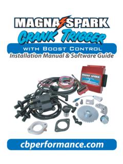
Transcription of Instruction Sheet 1 - cbperformance.net
1 Easy 2-wire install, connects directly to ignition coil. Compatible with most external spark boxes. Precision CNC Machined and hand assembled. Individually tested for reliability and performance. Accurate super hot spark from 50 RPM. all the way through 10,000 RPM. Hardened " diameter steel shaft with sealed roller bearing upper support and bronze bushed lower support for extreme stability at maximum RPM. Integrated Ignition Module design adds simplicity and reliability. Fully adjustable advance mechanism with easy-to-use spring and bushing design for a near infinite advance curve. Hot cranking spark as low as 50 RPM. High quality injection molded caps with brass terminals for long life and conductivity. Distributor is pre-curved to suit most popular engine combinations, so you make power and run properly right out of the box.
2 Available in your choice of Black or Polished. Please read this entire brochure prior to installing your CB Performance Products MAGNASPARK II distributor. MAGNASPARK II Installation Instructions: Parts List Warning: Before installing the CB Performance MAGNA- SPARK II Distributor, disconnect the negative battery cable. (1) MAGNASPARK II . Distributor Preparing Your Advance Curve (1) Advance Kit Your timing curve can consist of: Initial Advance, Centrifugal Advance. Initial Advance: Often referred to as "Base Timing", this is the initial (1) O-Ring timing set to the engine at idle. (1) Instruction Manual Centrifugal Advance: Often referred to as "Mechanical Advance". consists of a mechanism of weights, springs, cams and an advance stop bushing. As the engine RPM increases, the weights move creating advance.
3 The springs determine the rate of this advance and the advance stop bushing limits the total amount of centrifugal advance. Total Advance: This is the sum of initial advance and centrifugal advance. Example - Initial advance of 10 . plus centrifugal advance of 20 = 30 of Total Advance. Check Total Advance and Rate of Advance: With a timing light, you can determine the total advance and rate of advance. A degreed crank shaft pulley is required for this procedure. First, start the engine and set the idle speed. Using a timing light, rotate the MAGNASPARK II distributor until you reach your desired base timing (degrees of timing at idle). You may need to adjust the idle speed after setting base timing. Next, rev the engine until the timing stops advancing; this will be the total advance.
4 The RPM at which the timing stops advancing is the rate of advance. If desired, change the advance springs and/or stop bushings to adjust total and rate of advance. Setting Centrifugal Advance 40. Note: Degrees of advance and rate of advance are approximate. The mechanical advance uses tension springs to ADVANCE. STOP. control the rate of advance as RPM increases, the BUSHING. DEGREES ADVANCE. advance stop bushing determines the amount 30 Light Silver est & Blue Spring Small of total advance the distributor will have. Your Red/shing B u Blue hing MAGNASPARK II Distributor has three sets of Lightest Spring r Bus Silve shing 20 B u advance tension springs and four different Blue est /Larg advance stop bushings included. Blackshing B u Changing the Advance Springs: 10. Light Silver Spring You can mix or match the springs for your ad- Silver vance rate.
5 Your distributor has 3 sets of springs Heaviest Spring of which one set (Light Silver) are installed. The 0. 0 1000 2000 3000 4000 5000 6000 RPM. other 2 sets are in the parts kit and consist of a Heavy Silver Set and Blue set. The strongest to = Red = Silver = Blue = Black weakest spring ratings are as follows: Strong Rate = Heavy Silver Medium Rate = Light Silver 1 REMOVE. Light Rate = Blue ROTOR. Caution: Use eye protection when changing advance springs. 2 ADVANCE. SPRING. 1. Remove your distributor cap and rotor. 2. Carefully use needle-nose pliers to pull the spring and lift it off one of its posts. With one end of the spring off, the other ADVANCE. end will now freely lift off its post. 3 SPRING. POST. 3. Place desired spring on its inner post making sure it is seated in its receiver groove.
6 4. With your needle-nose pliers pull spring over its outer post making sure to secure this end in its receiver groove. Spring Combination Rate of Advance Heavy Silver + Heavy Silver Slowest (@ ~5500 RPM)*. Heavy Silver + Light Silver (@ ~4600 RPM)*. Heavy Silver + Blue (@ ~4000 RPM)*. Light Silver + Light Silver (@ ~3200 RPM)* (NOTE: Advanced Rate RPM's Light Silver + Blue (@ ~2800 RPM)* are approximate.). Blue + Blue Fastest (@ ~2500 RPM)*. *Verify with timing light 1. Changing the Advance Stop Bushing: The advance stop bushings are of different outer diameters. The smaller the diameter, the more advance it allows. The advance bushings are also color coded for ease of identification. A 'Red' advance stop bushing is pre-installed on your distributor and the parts kit will have 3 additional bushings.
7 Bushing Color Approx. Max. Advance in Crankshaft Degrees Red (smallest) 25 degrees Silver 22 degrees (installed). Blue 19 degrees Black (largest) 15 degrees 1. Remove your distributor cap. 2. Using a 7mm wrench remove the locknut and flat washer from the bottom #8-32 NUT. of the mechanical advance plate. #8 WASHER. 3. Remove the bushing and install the desired bushing. ADVANCE STOP BUSHING. 4. Re-install the washer and the locknut, securing the locknut tight. APPROXIMATE. Note: You may want to turn the distributor ADVANCE STOP CRANKSHAFT. BUSHING SIZE. upside down to ease in the installation of DEGREES. the advance stop bushing if the distributor RED - SMALLEST 25. is removed from the vehicle. SILVER 22. BLUE 19. BLACK - LARGEST 15. Locking out Centrifugal Advance: If you do not want to have any centrifugal ADVANCE ASSEMBLY (SHOWN UPSIDE DOWN).
8 Advance, you can lock it out by following this procedure with the distributor removed: 1. Remove the distributor drive gear 5 TURN SHAFT 180 . 3. retaining spring clip, and roll-pin. PUSH SHAFT. 2. Remove the distributor gear and UP APPROX. 2" 6. thrust washers. 3 MOVE SHAFT UP. APPROX. 2". 3. With distributor gear removed, 2 ALIGN ADVANCE. STOP BUSHING. REMOVE PIN WITH HOLE. push distributor shaft approximately DRIVE GEAR. 2 out of housing. RE-INSTALL. 4. Remove locknut, washer, and 1 4 7 HARDWARE. advance stop bushing (*NOTE: REMOVE. ROLL-PIN. TEMPORARILY. Advance stop bushing, springs, and REMOVE NUT AND #8 WASHER. WASHER AND. weights will not be used for this DISCARD ADVANCE #8-32 NUT. STOP BUSHING. application.). 5. Rotate distributor shaft 180 . 6. Align advance stop bushing stud with hole in the mechanical advance plate.
9 Push the distributor shaft back into the housing, making sure the advance stop bushing stud goes through the hole. 7. Re-install just the washer and locknut onto the advance stop bushing stud and make sure the locknut is tight. 8. Re-install distributor thrust washers, drive gear and roll-pin. Make sure retaining spring clip is re-installed. 2. Install Distributor and Spark Plug Wires 1. Slide distributor clamp over shaft of distributor. 2. Install "O" ring on distributor. 3. With distributor cap removed, install the distributor making sure it is seated. Secure distributor clamp to engine case stud. Rotate the distributor so the rotor tip lines up with #1 terminal on cap. Tighten distributor clamp. 4. Install distributor cap and tighten securely. 5. Install Spark Plug wires, making sure firing order is correct.
10 (see figure 1). 6. Connect MAGNASPARK II Distributor wire harness to ignition coil as shown in the diagrams. 7. Start engine and set desired timing with timing light. (See Page 1 Check Total Advance and Rate of Advance Section.). MAGNASPARK II MAGNASPARK II . Distributor Distributor RED SWITCHED BLACK. 12v RED +12v - POINTS. BLACK INPUT. AFTERMARKET. CDI BOX. IGNITION. Connection for Connection for KEY. Aftermarket CDI Box - MAGNASPARK II Ready-to-Run MAGNASPARK II COIL. Cylinder Firing Order - #1, #4, #3, #2. Attaching wires backwards on coil will result in immediate failure of FLYWHEEL SIDE. MAGNASPARK II Ignition Module. Damage to MAGNASPARK II . 1 ignition module due to improper 3 installation will void warranty 2 ** See Warranty Disclaimer 4 on Page 4 **. PULLEY SIDE. figure 1.
![Untitled-1 [cbperformance.net]](/cache/preview/e/5/f/7/b/1/6/5/thumb-e5f7b165dd01480669456e1777756b9f.jpg)
![Untitled-1 [cbperformance.net]](/cache/preview/7/d/b/9/5/1/f/c/thumb-7db951fc42a5d7c3972eada474bd816a.jpg)