Transcription of Instructions - The Global Leader in Fire and Gas Safety ...
1 Rev: 8/15 95-8714 InstructionsFlexSight LS2000 Line-of-SightInfrared Hydrocarbon Gas DetectorTable of ContentsappLIcatIon ..1opERatIon of Relays ..4optional communication Link ..4 History Magnetic Switch/calibration Line Identification ..5 Factory Reset ma current Loop output ..6 Heater control ..7 Status and Fault ..10 IMpoRtant Safety of Vapor(s) to be Detected ..15 System Location considerations ..15 Module Mounting an Existing Model opEcL with an LS2000 ..1924 VDc power Supply cable Wiring Size and Maximum Relays ..20 Wiring procedure ..23 Equipment Required ..24alignment procedure ..24aperture Kit for Short Range for using the HaRt Field Level Lamp ..28calibration overview ..28 Zero calibration ..28 Important calibration Initiation ..29calibration cleaning ..30 Functional caps and ..31 REpLacInG LS2000 tRanSMIttER/ REcEIVER ELEctRonIcS MoDuLE ..32 Module Replacement procedure.
2 32 DEVIcE REpaIR anD REtuRn ..34oRDERInG InFoRMatIon ..34alignment ..34 Spare parts ..34assistance ..34appEnDIx a - FM appRoVaL DEScRIptIon .36appEnDIx b - cSa cERtIFIcatIon c - atEx appRoVaL DEScRIptIon. 40appEnDIx D - IEcEx appRoVaL DEScRIptIon 43appEnDIx E - aDDItIonaL F - HaRt coMMunIcatIon ..47 ImportantBe sure to read and understand the entire instruction manual before installing or operating the gas detection system. This product is intended to provide early warning of the presence of a flammable or explosive gas mixture. Proper device installation, operation, and maintenance is required to ensure safe and effective FlexSight Line-of-Sight Infrared Hydrocarbon Gas Detector model LS2000 is a line-of-sight infrared gas detection system that provides continuous monitoring of combustible hydrocarbon gas concentrations in the range of 0 to 5 LFL-meters, over a distance of 5 to 120 meters.
3 Standard system outputs include an electrically isolated/non-isolated 4 20 mA dc current output with the ability to go below 4 mA to indicate fault conditions, and also HART and RS-485 Modbus communication. Alarm and fault relays are available as an option. The system consists of two stainless steel modules a transmitter and a receiver, along with mounting and alignment bracket. The receiver provides the measurement signal outputs, and is furnished with onboard status indication LEDs and an internal magnetic calibration switch. The transmitter houses a high quality xenon flash lamp and status indication LEDs. Both modules are powered from an external 24 volt DC supply and are equipped with microprocessor controlled heated optics to increase resistance to moisture and ice. Both modules must be installed at approximately the same elevation and must be aligned to point directly at one another.
4 No direct electrical interconnection between the two modules is LS2000 is certified explosion-proof for use in Class I, Division 1 and Division 2 hazardous areas, and has third party performance certification for methane, butane, and propane gas detection. It can be used as a stand-alone detector, or as part of a larger facility protection system using other Det-Tronics equipment. Detector Electronics Corporation 2016 Rev. 8/15 95-8714 INSTRUCTIONSFlexSight LS2000 Line-of-SightInfrared Hydrocarbon Gas ovERviEwThEORy Of OpERaTIONThe LS2000 transmitter module uses a Xenon flash lamp to produce a collimated IR light source. This light source illuminates the path between transmitter and receiver. The transmitter uses a filter to block visible light emissions and is eye safe. As flammable hydrocarbon gases intersect the light beam between the two modules, certain IR wavelengths are absorbed by the gas, while other IR wavelengths are not.
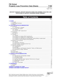
5 The amount of IR absorption is determined by the concentration of the hydrocarbon gas. A pair of optical detectors and associated electronics located in the receiver module measure the absorption. The change in intensity of the absorbed light (active signal) is measured relative to the intensity of light at a non-absorbed wavelength (reference signal). The microprocessor computes the gas concentration and converts the value into a 4-20 mA current output signal, which is then communicated to external control and annunciation systems. The gas concentration is indicated by a 4-20 mA signal, which corresponds to 0-5 LFL-meters. To better understand the concept of LFL-meters, refer to Figure 1, which shows how three gas clouds of different size and concentration would produce the same output of 1 LFL-meter by the line-of-sight gas detection system.
6 To convert a given LFL-m value to ppm-m for methane, propane or butane gas, refer to Table gaSESThe LS2000 is capable of detecting most hydrocarbon gases and vapors including methane, propane, and butane. Gas type and other operational parameters are selected via HART or Modbus communication. The LS2000 is factory calibrated to methane, propane, and butane, and comes from the factory set for methane. For detection of gases other than the three selection settings (methane, propane, and butane), performance characteristics / transfer curves are available. Please contact the factory for RaNgESThe LS2000 is offered in two detection ranges in order to meet customer needs, as listed below:Short Range 5-60 metersLong Range 30-120 metersFor installations with short separation distances (5-15 meters for the short range model and 30-40 meters for the long range model), the range reduction aperture kit (supplied) is required.
7 Refer to Aperture Kit for Short Range Applications section in this manual for details. The correct range for the LS2000 must be chosen to meet specific application needs. The detection range of the LS2000 pair is determined by the Receiver. Receiver units can be converted from long to short or short to long range in the field by replacing the front electronics module. A single transmitter model is used for both detection range OUTpUTThe LS2000 receiver module provides an analog 4-20 mA signal output. HART and RS-485 Modbus serial communication are available at either module. The 4-20 mA current loop corresponding to 0 5 LFL-meters is provided for connection to analog input devices such as gas controllers, logic controllers, or distributed control systems (DCS). To convert the mA reading to LFL-meters, use the following formula: mA Reading 4 X 5 = LFL-Meters 161M @ 100% LFL = 1 LFL-M2M @ 50% LFL = 1 LFL-M10M @ 10% LFL = 1 LFL-MLS2000 OUTPUT EQUALS 1 LFL-M IN ALL THREE SCENARIOSA2665 Figure 1 Detector Response to three Gas clouds of Different Size and length (m)CloudConcentration (lfl)CloudConcentration (v/v, by volume)CloudConcentration (ppm)lfl-mppm-mMethane1100% 1 LFL-m to ppM-m RElaySThe LS2000 can be furnished with factory installed relays two programmable alarm relay outputs and one fault relay output.
8 All relays are sealed and provide form C (NO/NC) contacts. The high and low alarm relays are programmable, and can be set for latching / non-latching operation, and a normally energized / de-energized coil (see Table 3). The low alarm cannot be set above the high alarm threshold. Alarm configuration can be done with the HART or Modbus interface. The onboard multi-color LEDs indicate a LOW alarm condition via a flashing red color, and a HIGH alarm condition via a steady red color. Latched alarms can be reset using the internal magnetic switch, an external switch connected to the calibration line terminal, a HART Field Communicator, or Modbus communication. A short-duration magnetic switch activation of one second will reset latched alarms. Holding the magnetic switch closed for a three second duration will start the calibration sequence.
9 When the optional relays are ordered, the LS2000 receiver is certified for Ex d operation. OpTIONal COmmUNICaTION lIN kBy connecting the transmitter and receiver via a three-wire shielded cable, an optional communication link can be created between the two communication link offers the following advantages:1. Single point system diagnostics The link offers the ability to view device variables of the receiver while connected to the transmitter, or vice versa (using a HART handheld or Modbus device). These variables include signal strength, status, and configuration parameters such as alarm set points, heater settings, gas type, etc. 2. Dynamic lamp power The link enables the system to optimize lamp power per the application. This optimization only happens during the zero calibration Synchronized LEDs on each device can signal a common system status condition.
10 Without the link, the transmitter is unable to signal alarm Transmitter variables can be configured via connection to the receiver. Configurable transmitter variables include lamp power and heater setpoints in the receiver cannot be changed from the The communication link provides the ability to initiate Calibration from either the transmitter or retrofit applications where an inter-connecting wire is not available or possible, the system can operate without the link. If the link is not connected, the system will not indicate a link fault. A link fault feature can be enabled (using a HART handheld or Modbus device), which will indicate a fault if the link is broken. The link fault can only be detected and annunciated by the receiver. NoTeThe default setting for the link fault feature is third-party performance and hazardous location approvals apply with and without the communication link lOgSNon-volatile memory is provided in the receiver to save a record of the 100 most recent calibrations and 1000 most recent alarm/fault events.