Transcription of Instrument Engineer's Handbook for DURCO Quarter-turn ...
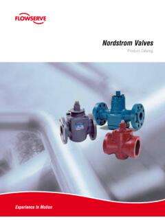
1 1 Instrument Engineer's Handbook for DURCO Quarter-turn Control Valves flowserve Corporation Flow Control Division 1978 Foreman Drive Cookeville, TN 38501 FCD AXAMS0045-00 (AUTO-45) 2 Revision October 2011 flowserve Corporation, Flow Control Division, Cookeville, Tennessee, extends its appreciation to the Instrument Society of America for its permission to adapt Standard , Instrument Society of America, 1985 and Control Valve Sizing by Driskell , Instrument Society of America, 1976. A valuable reference for further study of control valves is the ISA Handbook of Control Valves, Second Edition, 1976. Instrument Engineer s Handbook for DURCO Control Valves Preface This manual on control valve sizing brings together the mathematical tools required to select DURCO valves properly for control valve applications. The equations presented for liquids, gases, and steam are based on the ISA standard and are divided into sections to simplify manual calculation for the more common sizing problems.
2 Examples of each type are presented for further comprehension. The selection of a correct valve size as mathematically determined depends on accurate knowledge of the actual flowing data. Frequently, one or more of the operating conditions are arbitrarily assumed. Most errors in control valve sizing are due to incorrect assumptions. Generally speaking, the tendency is to make the valve too large to be on the "safe side". Combining these so called "safety factors" can result in a valve which is oversized and one which contributes to poor control and system instability. There is no substitute for good engineering judgment. Only good common sense combined with experience can bring forth an acceptable solution in valve sizing. Control valve applications vary in degree from simple to complex. On occasion, guidance and assistance in selecting the proper control valve may be required.
3 3 table OF CONTENTS Topic Page SECTION 1 How to Size Valves 5 Liquid Sizing 6 Gas Sizing 14 Steam Sizing 17 Frequently Used Formula Conversions 20 SECTION 2 Noise Abatement 21 Hydrodynamic noise 22 SECTION 3 Cv and Torque Tables for Valve and Actuator Sizing 26 Sleeved Plug Valve -- G4, G4B Marathon, TSG4, TSG4Z (standard port only) Cv 28 Sleeved Plug Valve -- G4, G4B Marathon (use for standard and V-port) Sizing Torque 29 Triple Sealed Sleeved Plug Valve --TSG4, TSG4Z (use for standard and V-port) Sizing Torque 29 Sleeved Plug Valves (V-port only) -- G4, G4B Marathon, TSG4, TSG4Z Cv 30 MG4 Sleeveline Plug Valves -- Multi-Port Plug Cv 31 Port-Seal/Sleeved Mach 1 Valve V-Port Cv 32 Port-Seal/Sleeved Mach 1 Valve Standard Port Cv 32 Port-Seal/Sleeved Mach 1 Valve Sizing Torque 32 Fluorocarbon Lined Plug Valves (standard port only) -- T4E Cv 33 Fluorocarbon Lined Plug Valves -- T4E (use for standard port and V-port plugs) Sizing Torque 34 Fluorocarbon Lined Plug Valves (V-port only)
4 -- T4E Cv 35 BX2001 -- Big Max Butterfly Valves -- ANSI Class 150# Series Cv 36 BX2001 -- Big Max Butterfly Valves -- ANSI Class 150# Series Standard PFA/Viton Seat Sizing Torque 37 BX2001 -- Big Max Butterfly Valves -- ANSI Class 150# Series Firesealed, Standard PFA/Inconel & UHMWPE Seats only Sizing Torque 37 BX2001-- Big Max Butterfly Valves -- ANSI Class 150# Series -- TriFlex Metal Seat (70 F) Sizing Torque 38 BX2001 -- Big Max Butterfly Valves -- ANSI Class 150# Series -- TriFlex Metal Seat (800 F) Sizing Torque 38 BX2001 -- Big Max Butterfly Valves -- ANSI Class 150# Series -- TriFlex Metal Seat (1000 F) Sizing Torque 38 BTV Valve -- Fluorocarbon Lined Butterfly Valves -- ANSI Class 150# Series Cv 39 BTV Valve -- Fluorocarbon Lined Butterfly Valves -- ANSI Class 150# Series Sizing Torque 40 BUV Valve -- UHMWPE Lined Butterfly Valves -- ANSI Class 150# Series Sizing Torque 40 Atomac AKH3 Valve -- Standard Port Ball Valve -- Lined Cv 41 Atomac AKH3E Valve -- V- Port Ball Valve -- Lined Cv 41 Atomac CAKH3V Valve C-Ball Standard Port Ball Valve Lined Cv 41 Atomac AKH3 Valve -- Standard Port Ball Valve -- Lined -- Clean / Clear Service Sizing Torque 42 Atomac AKH3 Valve -- Standard Port Ball Valve -- Lined -- Slurry Service Sizing Torque 42 Atomac CAKH3V Valve C-Ball Standard Port Ball Valve Lined
5 Sizing Torque 42 Atomac AKH2 Valve -- Standard Port Ball Valve -- Lined Cv 43 Atomac AKH2 Valve -- Full Port Ball Valve -- Lined -- Clean / Clear Service Sizing Torque 44 Atomac AKH2 Valve -- Full Port Ball Valve -- Lined -- Slurry Service Sizing Torque 44 Atomac AKH5 Valve -- Standard Port Ball Valve -- Ceramic Lined Cv 45 Atomac AKH5 Valve -- Standard Port Ball Valve -- Ceramic Lined (Liner & Ball) Clean / Clear Service Sizing Torque 45 Atomac AKH5 Valve -- Standard Port Ball Valve -- Ceramic Lined (Liner & Ball) -- Slurry Service Sizing Torque 45 4 Atomac AKH2A Valve -- Full Port Ball Valve -- Lined Cv 46 Atomac AKH2A Valve -- Full Port Ball Valve -- Lined -- Clean / Clear Service Sizing Torque 46 Atomac AKH2A Valve -- Full Port Ball Valve -- Lined -- Slurry Service Sizing Torque 46 Atomac AKH6 Valve -- Tank Drain Ball Valve -- Lined Cv 47 Atomac AKH6 Valve -- Tank Drain Ball Valve -- Lined -- Clean / Clear Service Sizing Torque 47 Atomac AKH6 Valve -- Tank Drain Ball Valve -- Lined -- Slurry Service Sizing Torque 47 Atomac AMP3 Valve -- 3-Way Ball Valve -- Lined Cv 48 Atomac AMP3 Valve -- 3-Way Ball Valve -- Clean / Clear Service Sizing Torque
6 48 Atomac AMP3 Valve -- 3-Way Ball Valve -- Slurry Service Sizing Torque 48 SECTION 4 Reference Data 49 Pressure concepts and types 50 Useful equivalents 50 Mass rate 51 Mass rate liquids 52 Vacuum equivalents 52 Temperature conversions 52 Physical constants of common industrial substances 53 Liquid velocity determination 56 Steam recommendations 57 Saturated and superheated steam tables 58 Values of K 60 Specific weight vs. temperature 61 Compressibility charts 62 ISA control valve sizing terminology, formulas and nomenclature 65 5 Section One 6 LIQUID SIZING Liquid flow through DURCO valves may be predicted by using the thermodynamic laws of fluid flow and the standards established in this manual by the flowserve Corporation.
7 There are two basic requirements that must be determined to properly size DURCO control valves; first is the Cv required and second is the allowable pressure drop for a given service and valve. Proper selection of any control valve requires some basic information that may or may not be readily available. Ideally, we would like to: 1) Get a general description of what is to be accomplished or a data sheet if possible. 2) Have the following data provided. a) Inlet pressure. b) Temperature maximum and minimum. c) Process fluid. d) Flow rates - maximum, normal and minimum. e) Vapor pressure. f) Pipeline size - schedule and material. g) Pressure drop - minimum, normal and maximum. h) Specific gravity. i) Critical pressure. The following formulae shall be used in sizing DURCO Valves. Q Where: Cv = Flow coefficient required.
8 Q = Flow in gpm. = Specific gravity P = Pressure drop in psi. Definition: Cv, is numerically equal to the number of gallons of water that will flow through a valve in one minute with water at 60OF and a one psi differential pressure across the valve. Pallow = FL 2(P1-rcPV) Where: Pallow = allowable pressure drop in psi. FL2 = Recovery coefficient from CV chart. rc = Critical pressure ratio from rc chart. PV = Vapor pressure in psia. CV = Q Note: This formula should be used when Pactual Pallow , where: Pactual = P1-P2 ..GSP Cv= (for choked flow) ..GSPallow 7 DETERMINING THE REQUIRED Cv Formula is the general-purpose equation for most liquid sizing applications. This formula utilizes the actual pressure drop or the inlet pressure minus the outlet pressure, to calculate the required Cv.
9 Examination of the formula indicates that "if the pressure drop increased, the flow should also increase." There is, however, a point where further decreases in P2 results in no change in flow rate and is referred to as "Choked Flow." Therefore, the actual P no longer applies and a maximum Pallow must be substituted to calculate the required Cv,(equation ). Choked flow results from flashing or cavitation and could cause damage to the valve and/or piping. When solving a liquid sizing application, consider some or all of the following points to determine if Pallow should be used. 1) If the inlet pressure (P1) is relatively close to the vapor pressure. 2) If the outlet pressure (P2) is relatively close to the vapor pressure. 3) If the actual pressure drop is large when compared to the inlet pressure. This means that if there is any doubt that the liquid service is in close proximity to choked flow, the Pallow must be calculated and compared to Pactual (see section on cavitation and flashing beginning on page 10).
10 Using a valve smaller than line size will contribute to errors in the required Cv, due to losses caused by the expanders and reducers. flowserve has calculated this effect on CV, and printed the results for your convenience (see Section 2). Should the need arise to calculate the corrected CV, for various combinations we have supplied a catalog of formulae from ISA standards . When an incompressible fluid has a high viscosity and/or low velocity, laminar flow may exist. The CV previously discussed assumed turbulent flow and must be multiplied by a correction factor (FR) to obtain the actual flow coefficient. Generally speaking, if the viscosity is less than SAE 10 motor oil (~30cp), this factor may be neglected. CV CALCULATIONS PROCEDURE 1) Using the given flow conditions, calculate the CV, using equation 2) Select a nominal valve size from the sizing charts based on the calculated CV.
