Transcription of INSTRUMENTATION AND CONTROL TUTORIAL 2 …
1 INSTRUMENTATION AND CONTROL TUTORIAL 2 ELECTRIC ACTUATORS This is a stand alone TUTORIAL on electric motors and actuators. The TUTORIAL is of interest to any student studying CONTROL systems and in particular the EC module D227 CONTROL System Engineering. On completion of this TUTORIAL , you should be able to do the following. Describe the advantages and disadvantages of electric actuation. Describe how motors are used for actuation. Explain how motors are used for actuation. Explain the basic principles of stepper motors. Explain how linear motion is obtained. Explain in some detail the principles of various types of servo motors. If you are not familiar with INSTRUMENTATION used in CONTROL engineering, you should complete the tutorials on INSTRUMENTATION Systems.
2 In order to complete the theoretical part of this TUTORIAL , you must be familiar with basic electrical science. 1. INTRODUCTION Electrically actuated systems are very widely used in CONTROL systems because they are easy to interface with the CONTROL systems which are also electric and because electricity is easily available unlike fluid power which require pumps and compressors. The advantages of electric systems are Electricity is easily routed to the actuators; cables are simpler than pipe work. Electricity is easily controlled by electronic units Electricity is clean. Electrical faults are often easier to diagnose. The disadvantages of electric actuators are Electrical equipment is more of a fire hazard than other systems unless made intrinsically safe, in which case it becomes expensive.
3 Electric actuators have a poor torque - speed characteristic at low speed. Electric actuators are all basically rotary motion and complicated mechanisms are needed to convert rotation into other forms of motion. The power to weight ratio is inferior to hydraulic motors. There are three types of motors used in CONTROL applications. motors. motors. Stepper motors. 2. MOTORS motors are mainly used for producing large power outputs at a fixed speed. Typically these are 1420 or 2900 rev/min. Such motors are controlled by switching them on and off. Increasingly, speed CONTROL is being used with motors on applications such as pumps where it is found to be more economical to CONTROL the flow rate by changing speed rather than by opening or closing a pipe line valve.
4 Speed CONTROL is achieved electronically by varying the frequency or by chopping the power supply. Figure 1 These motors are usually geared down in order to produce a greater torque and increase the CONTROL range. They may also have the rotation converted into linear movement by a lead screw mechanism. 2 Figure 2 Lead screws are used to convert rotation into linear motion as shown. Rotation screws the carriage back and forth along the lead screw. 3. MOTORS Direct current motors are more widely used in CONTROL applications and they are usually referred to as SERVO MOTORS. These are covered in detail later in the TUTORIAL . The development of more powerful magnets is improving the power to weight ratio but they are still not as good as hydraulic motors in this respect.
5 Servo motors usually have a transducer connected to them in order to measure the speed or angle of rotation. The diagram shows a typical arrangement. Figure 3 4. STEPPER MOTORS Basically a stepper motor rotates a precise angle according to the number of pulses of electricity sent to it. Because there is confidence that the shaft rotates to the position requested, no transducer is needed to measure and check the position and so they are common on open loop systems. There are 3 types of stepper motor in common use and these are Figure 4 1. The PERMANENT MAGNET TYPE. 2. The VARIABLE RELUCTANCE TYPE. 3. The HYBRID TYPE. 3 THE PERMANENT MAGNET TYPE. The rotor is a permanent magnet with a North and South poles as shown. Two pairs of poles are placed on the stator and energised to produce a pattern of N - S - N - S (starting at the top).
6 The rotor will take up a position in between the poles due to equal and opposite torques being exerted on it. Figure 5 If the polarity of both pairs of poles are reversed the pattern will change to S - N - S - N and the rotor will flip 45o to a new position of balance. In order to obtain more steps, more pairs of poles are used but there are only two windings. Reversing the polarity of both windings moves the rotor on one step. Stepping is produced by simply reversing the polarity. Figure 6 The rotor is held in position even when the poles are not energised. In order to obtain many steps, the poles are often stacked one behind the other and not in a single ring. The number of steps may also be increased by using a gear box on the output shaft.
7 Figure 7 VARIABLE RELUCTANCE TYPE The rotor is constructed of soft iron with a number of teeth which are unequal in number to the number of poles on the stator. The stator has multiple poles which are energised by several separate phases. The diagram shows a system with three phases. Figure 8 When a current is applied to the stator windings, the rotor aligns itself in the position of least magnetic reluctance. This position depends upon the number of phases energised. The rotor retains very little magnetism so there is no holding torque when the current is removed. The number of steps is given by N = SR/(S-R) where S is the number of stator slots and R the number of rotor slots. 4 HYBRID MOTORS Hybrid motors are a combination of the last two types.
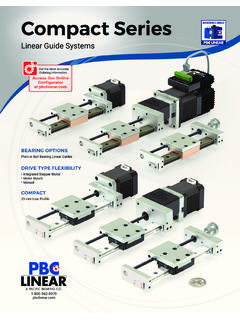
8 Each pole is divided into slots as shown. The rotor has two sets of slots, one behind the other with one set offset to the other by 1/2 slot pitch. The rotor is magnetised longitudinally. This produces a high resolution. Figure 9 In general all stepper motors are controlled electronically. Figure 10 5. LINEAR ELECTRIC ACTUATORS Figure 11 In recent years, a range of linear electric actuators have been developed to perform functions similar to hydraulic and pneumatic cylinders. These are based on a motor driven lead screw. The motors may be AC or DC. The speed of the motor is reduced with a compact gear box before driving the lead screw. Actuators have been developed with thrusts up to 15 kN and strokes up to 3 metres. Now we will go on and examine the details of Motors.
9 5 6. DETAILED ANALYSIS OF MOTORS The theory of electrical machines is based on two basic discoveries called the motor principle and the generator principle. In any given machine, the two go together. THE MOTOR PRINCIPLE When a conductor is placed in a magnetic field at a right angle to it and current flows in the conductor, a force is exerted on the conductor. The force F (Newton) is related to the flux density B (Tesla), the current I (Amps) and the length l (metres) by the formula F = B I The flux density is the flux per unit area so B = /A where is the flux in Webers and A the cross sectional area of the flux path in m2. This force acting at a radius produces the torque T to rotate the motor. The current in the conductor is Ia.
10 Figure 12 For a given motor the area, lengths and radius are constant so the equation reduces to T = k1 Ia .. (1) THE GENERATOR PRINCIPLE When a conductor moves at velocity v m/s through a flux of density B Tesla, an is generated in the conductor such that E = B v. This opposes the flow of the applied current so a forward voltage is required to overcome it. This effect is produced in the conductors of motors as well as generators since the motor has moving conductors passing through a flux. The conductor is part of a coil rotating at speed N rev/s and v = 2 NR For a given motor in which the area and length may be considered constant, the equation becomes E = K2 N.