Transcription of Insulation monitoring device for unearthed AC/DC control ...
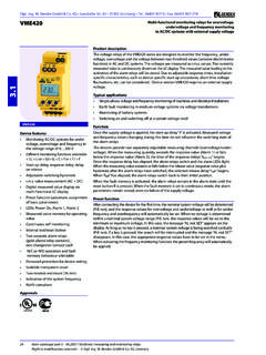
1 42 Main catalogue part 1 monitoring IR425 Insulation monitoring device for unearthed AC/DC control circuits (IT systems)A-ISOMETER IR425 device features Insulation monitoring for control circuits AC/DC V Two separately adjustable response values Preset function (automatic assignment of basic parameters) Connection monitoring system/earth LEDs: Power On, Alarm 1, Alarm 2 Internal/external test/reset button Two separate alarm relays (one changeover contact each) N/O or N/C operation, selectable Fault memory behaviour, selectable Self monitoring with automatic alarm message Multi-functional LC display Adjustable response delay Two-module enclosure (36 mm)ApprovalsProduct descriptionThe A-ISOMETER of the IR425 series is designed to monitor the Insulation resistance of unearthed AC/DC control circuits (IT systems) V.
2 DC components existing in AC/DC systems do not influence the operating characteristics. An external supply voltage allows de-energized systems to be monitored AC/DC control circuits in the industrial sector, mechanical engineering, power plants, elevators, automation systems etc. AC/DC control and auxiliary circuits in accordance with IEC 60204-1/DIN EN 60204-1 Electrical equipment of machines AC/DC auxiliary circuits in accordance with DIN VDE 0100-725 (VDE 0100-725) Smaller AC/DC IT systems such as lighting systems, mobile generatorsFunctionThe currently measured Insulation resistance is indicated on the LC display.
3 In this way any changes, for example when circuits are connected to the system, can be recognized easily. When the value falls below the preset response values, the response delay "ton starts. Once the response delay "ton" has elapsed, the "K1/K2" alarm relays switch and the alarm LEDs "AL1/AL2" light up. Two separately adjustable response values/alarm re-lays allow a distinction to be made between "prewarning" and "alarm". If the Insulation resistance exceeds the release value (response value plus hysteresis), the alarm relaysreturn to their initial position. Insulation faults are distinguished according to AC and DC faults (indication ).
4 If the fault memory is enabled, the alarm relays remain in the alarm state until the reset button is pressed or until the supply voltage is switched off. Thedevice function can be tested using the test button. The parameterization of the device can be carried out via the LC display or the function keys integrated in the front monitoringThe connections to the system (L1 / L2) and to earth (E / KE) are either automaticallychecked every 24 h, or by pressing the test button or when supply voltage has beenconnected. In case of interruption of a connecting lead, the alarm relays K1 / K2 switch, the LEDs ON // AL1 // AL2 flash and the following message appears on the display:" indicating a fault in the connecting leads to the system," indicating a fault in the connecting leads to PE.
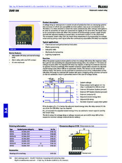
5 After eliminating the fault, the alarm relays return to their initial position either automa-tically or by pressing the reset functionAfter connecting the device for the first time, the nominal system voltage is measured and the response values are set principleThe A-ISOMETER IR425 uses the AMP measuring W. Bender GmbH & Co. KG Londorfer Str. 65 35305 Gr nberg Tel.: 06401 807-0 Fax: 06401 807-259 Right to modifications reserved ! W. Bender GmbH & Co. KG, Germany Main catalogue part 1 monitoring IR425 Operating elementsWiring diagram1 - Power ON LED "ON", flashes in case of interruption of theconnecting leads earth/ KE or L1 / - Alarm LED "AL1 , lights when the value falls below the setresponse value Alarm 1 and flashes in case of interruptionof the connecting leads earth/KE or L1/L2).
6 3 - Alarm LED "AL2 , lights when the value falls below the setresponse value Alarm 2 and flashes in case of interruptionof the connecting leads earth/KE or L1 - LC display5 - Test button "T": To call up the self up key: Parameter change, to move up in the - Reset button "R": To delete stored Insulation fault alarms Arrow down key: Parameter change, to move down in the - MENU key: To call up the menu key: To confirm parameter - Supply voltage US (see ordering information) via fuse 2 - Separate connection of E, KE to PE3 - Connection to the IT system being monitored: AC: Connect terminals L1, L2 to conductor L1, L2.
7 DC: Connect terminal L1 with L+ and L2 with - Alarm relay K1: Alarm 15 - Alarm relay K2: Alarm 26 - Combined external test and reset button "T/R": Short-time pressing: (< s) = RESET Long-time pressing (> s) = TEST7 - Line protection by a fuse in accordance with IEC 60364-4-43 (6 A fuse recommended). In case of supply (A1/A2) from an IT system, both lines have to be protected by a Main catalogue part 1 monitoring IR425 Switching elements Number of switching elements 2 x 1 changeover contactOperating principle N/C or N/O operation (N/O operation)*Electrical service life, number of cycles data acc.
8 To IEC 60947-5-1 Utilization category AC-13 AC-14 DC-12 DC-12 DC-12 Rated operational voltage 230 V 230 V 220 V 110 V 24 VRated operational current 5 A 3 A A A 1 AMinimum current 1 mA at AC/DC 10 VEnvironment/EMC EMC IEC 61326 Operating temperature - 25 + 55 C Climatic class acc. to IEC 60721 Stationary use (IEC 60721-3-3) 3K5 (except condensation and formation of ice)Transport (IEC 60721-3-2) 2K3 (except condensation and formation of ice)Long-time storage (IEC 60721-3-1) 1K4 (except condensation and formation of ice)Classification of mechanical conditions IEC 60721 Stationary use (IEC 60721-3-3) 3M4 Transport (IEC 60721-3-2) 2M2 Long-time storage (IEC 60721-3-1) 1M3 ConnectionConnection properties screw-type terminalsrigid/flexible/conductor sizes mm2/24-12 AWGM ulti-conductor connection (2 conductors with the same cross section)
9 Rigid/flexible mm2 Stripping length mmTightening torque NmOther Operating mode continuous operationMounting any positionDegree of protection, internal components (IEC 60529) IP30 Degree of protection, terminals (IEC 60529) IP20 Enclosure material polycarbonateDIN rail mounting acc.
10 To IEC 60715 Screw mounting 2 x M4 with mounting clipProduct standards DIN EN 61557-8: 1998-05, EN 61557-8: 1997-03 IEC 61557-8: 1997-02, ASTM F 1669M-96 (2002)Operating manual BP103005 Weight 150 g* = factory settingTechnical data A-ISOMETER IR425 Insulation coordination acc.