Transcription of Interfacing withLiquid Crystal Displays V1 - …
1 1 A Comprehensive Guide on LCD Interfacing to Arduino Board with different code examples. Learn Arduino LCD Interfacing Interfacing withLiquid Crystal Displays 2 Table of Contents Solution1:Setting Up the LCD .. 4 : Parts You ll Need for This Chapter: .. 4 : Using the LiquidCrystal Library to Write to the LCD .. 7 : Adding Text to the display .. 8 : Creating Special Characters and Animations .. 9 Solution 2: Temperature Control .. 13 : Building a Personal Thermostat .. 13 : Setting Up the Hardware .. 13 : Displaying Data on the LCD .. 14 : Adjusting the Set Point with a Button .. 16 : Adding an Audible Warning and a Fan .. 17 : Bringing It All Together: The Complete Program .. 18 Solution 3: display Text and Character.
2 21 : String variables: String type vs. char type .. 21 : Parallel character LCDs: the Hitachi HD44780 .. 23 : 4-bit or 8-bit? .. 23 : Library and functions .. 23 : Circuit diagram .. 24 : Connecting everything up in 4-bit mode .. 24 : Sketch for writing to the Hitachi HD44780 .. 26 : Upload and test .. 27 Solution 4:UsingLCD+Keypad Shield for Arduino .. 28 : How to use 16 2 Character LCD + 6-buttons Keypad Shield ? .. 28 : Pins Assignment .. 29 : Application Ideas .. 29 Solution 5:Arduino Code Examples withLCD+Keypad Shield .. 32 : Formatting Text .. 32 : Displaying Special Symbols .. 35 : Creating Custom Characters .. 38 : Displaying Symbols Larger Than a Single 39 Solution 6: Using an Arduino as an LCD clock.
3 42 : The Components .. 43 : Connecting It All Together .. 43 3 : LCD Connection where Pin 1 on LCD is far left .. 43 : Wiring up the RTC Module: .. 44 : Checking It Works .. 45 : Setting the Time in the RTC .. 45 : Uploading the Time Sketch .. 47 7. Appendix .. 49 : LCD Application Manual .. 49 : HandsOn Technology Products Quality Commitments .. 49 4 Solution1:Setting Up the LCD : Parts You ll Need for This Chapter: Arduino Uno USB cable (A to B for Uno) Speaker Pushbuttons (n2) Small DC fan 16x2 character LCD resistors (n2) 10k resistors (n2) 150 resistor 10k potentiometer I2C temperature sensor Jumper wires Breadboard In this chapter, you learn how to connect an LCD to your Arduino, and you learn how to use the ArduinoLiquidCrystal library to write text and arbitrary custom characters to your LCD.
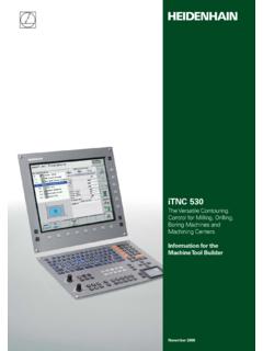
4 After you have the basics down, you add some components to make a simple thermostat capable of obtaining local temperature data, reporting it to you, and controlling a fan to compensate for heat. An LCD will give you live information, a speaker will alert you when the temperature is getting too hot, and the fan will turn on to automatically cool you down. Figure 1-1: LCD with Headers soldered on To complete the examples in this chapter, we use a parallel LCD screen. These are extremely common and come in all kinds of shapes and sizes. The most common is a 16 2 character display with a single row of 16 pins (14 if it does not have a backlight). In this chapter, we use a 16-pin LCD display that can show a total of 32 characters (16 columns and 2 rows).
5 If your display didn t come with a 16-pin header already soldered on, you need to solder one on so that you can easily install it in your breadboard. With the header successfully soldered on, your LCD should look like the one shown in Figure 1-1, and you can insert it into your breadboard. Refer to Figure 1-2 board layout for complete pins assignment. 5 : Figure Board layout and pins of the Arduino Uno Next, you wire up your LCD to a breadboard and to your Arduino. All of these parallel LCD modules have the same pin-out and can be wired in one of two modes: 4-pin or 8-pin mode. You can accomplish everything you might want to do using just 4 pins for communication; that s how you ll wire it up. There are also pins for enabling the display , setting the display to command mode or character mode, and for setting it to read/write mode.
6 Table 1-1 describes all of these pins. PIN NUMBER PIN NAME PIN PURPOSE 1 VSS Ground connection 2 VDD +5V connection power supply 3 VO Contrast adjustment (to potentiometer) 4 RS Register selection (Character vs. Command) 5 RW Read/write 6 EN Enable 7 D0 Data line 0 8 D1 Data line 1 9 D2 Data line 2 10 D3 Data line 3 11 D4 Data line 4 12 D5 Data line 5 13 D6 Data line 6 14 D7 Data line 7 15 A Backlight anode 16 K Backlight cathode Table 1-1: Parallel LCD Pins assignment 6 Here s a breakdown of the pin connections: The contrast adjustment pin changes how dark the display is. It connects to the center pin of a potentiometer. The register selection pin sets the LCD to command or character mode, so it knows how to interpret the next set of data that is transmitted via the data lines.
7 Based on the state of this pin, data sent to the LCD is either interpreted as a command (for example, move the cursor) or characters (for example, the letter a). The RW pin is always tied to ground in this implementation, meaning that you are only writing to the display and never reading from it. The EN pin is used to tell the LCD when data is ready. Data pins 4~7 are used for actually transmitting data, and data pins 0~3 are left unconnected. You can illuminate the backlight by connecting the anode pin to 5V and the cathode pin to ground if you are using an LCD with a built-in resistor for the backlight. If you are not, you must put a current-limiting resistor in-line with the anode or cathode pin.
8 The datasheet for your device will generally tell you if you need to do this. We can connect the communication pins of the LCD to any I/O pins on the Arduino. In this chapter, they are connected as shown in Table 1-2. LCD PIN ARDUINO Uno PIN NUMBER RS Pin 2 EN Pin 3 D4 Pin 4 D5 Pin 5 D6 Pin 6 D7 Pin 7 Table 1-2: Communication Pins Connections Reference the wiring diagram shown in Figure 1-3 and hook up your LCD accordingly. 7 Figure 1-3: LCD wired to breadboard and Arduino Now your LCD is ready for action! Once you get the code loaded in the next section, you can start displaying text on the screen. The potentiometer will adjust the contrast between the text and the background color of the screen.
9 : Using the LiquidCrystal Library to Write to the LCD The Arduino IDE includes the LiquidCrystal library, a set of functions that makes it very easy to interface with the parallel LCD that you are using. The LiquidCrystal library has an impressive amount of functionality, including blinking the cursor, automatically scrolling text, creating custom characters, and changing the direction of text printing. This chapter does not cover every function, but instead gives you the tools you need to understand to interface with the display using the most important functions. You can find descriptions of the library functions and examples illustrating their use on the Arduino website: 8 : Adding Text to the display In this first example, we add some text and an incrementing number to the display .
10 This exercise demonstrates how to initialize the display , how to write text, and how to move the cursor. First, include the LiquidCrystal library: #include < > Then, initialize an LCD object, as follows: LiquidCrystallcd (2, 3, 4, 5, 6, 7); The arguments for the LCD initialization represent the Arduino pins connected to RS, EN, D4, D5, D6, and D7, in that order. In the setup, you call the library s begin() function to set up the LCD display with thecharacter size. (The one we are using is a 16 2 display , but you might be using another size, such as a 20 4). The arguments for this command represent the number of columns and the number of rows, respectively: (16, 2); After doing that, you can call the library s print() and setCursor()commands to print text to a given location on the display .