Transcription of INTRODUCTION KEY FEATURES / BENEFITS - …
1 INSTRUCTION MANUAL. INTRODUCTION . The PMP Series peristaltic metering pump system is designed to dispense a variety of cleaning and sanitizing chemicals. Positive, accurate metering of liquids can be triggered manually or by a process control signal. The PMP Series offer variable speed output or fixed speed output with a choice of programmable limit-timer or repeating cycle timer. PMP is built with Knight's field proven, long-life peristaltic pumps. Moisture sensitive motor and controllers are enclosed in a corrosion resistant, watertight, powder coated case that stands up well for indoor and outdoor applications. KEY FEATURES / BENEFITS . Auto-Start or Optional Manual Button Activation Watertight, Secure Locking Enclosure Long-Life Peristaltic Pumps Water Resistant Case w/ D Shaped Silicone Gasket PMP-800 Series Long Lasting Squeeze Tube Fixed or Variable Pump Speed Wide Range of Flow Rates Microprocessor, Push Button Programming Available Pumps Up to 30 PSI. Self Priming, Easy to Service Pump Lockout Option APPLICATIONS.
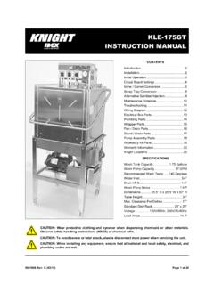
2 FOOD & BEVERAGE PROCESSING PLANTS: CIP/COP, Grease Traps, Sewage Treatment DAIRY: Pipeline Cleaning/Sanitizing, Teat Dip Chemical, Wash Pen Chemical Injection INDUSTRIAL: General Cleaning, Machinery Lubrication, Cooling Towers, Boilers TRANSPORTATION: Car Wash Stations PMP-900 Series Remote Activator 0900381 Rev: G (10/12) Page 1 of 12. CAUTION: Wear protective clothing and eyewear when dispensing chemicals or other materials. Observe safety handling instructions (MSDS) of chemical mfrs. CAUTION: To avoid severe or fatal shock, always disconnect main power when servicing the unit. CAUTION: When installing any equipment, ensure that all national and local safety, electrical, and plumbing codes are met. Page 2 of 12 0900381 Rev: G (10/12). RECOMMENDED OPERATING PARAMETERS. Pump Model Duty Cycle Maximum Pump Run Maximum Lift Maximum Head Time (Suction) Pressure PMP-500 Series 50% 5 Minutes 10 Feet (3 Meters) 30 PSI (2 Bar). PMP-800 Series 50% 5 Minutes 10 Feet (3 Meters) 30 PSI (2 Bar).
3 PMP-900 Series 10% 5 Minutes 10 Feet (3 Meters) 30 PSI (2 Bar). NOTES: The duty cycles and maximum pump run time specified above can be exceeded, however in doing so the life of the squeeze tube, roller block and motor will be reduced. Fixed speed (AC drive) pumps have a thermal cut-out that will stop the pump if it overheats. The duty cycle of the pump and ambient temperature contribute greatly to the overall run time capability, regardless of the maximum allowable time that can be set on the circuit board (if so equipped). If the thermal cut-out activates to stop the pump, the pump must cool down before it can resume normal operation. SPECIFICATIONS. Enclosure: Powder coated stainless steel. Pump Drive: Shaded pole AC or variable DC. Squeeze Tube: Material available for most chemical applications. Control: Limiting timer or repeating cycle timer. Power Supply: 115 VAC/60HZ, 230 VAC/60HZ, 230 VAC/50HZ. Dimensions: PMP-500: H x W x 5 D ( x x ). PMP-800: H x W x 5 D ( x x ). PMP-900: H x 8 W x D ( x x ).
4 THEORY OF OPERATION. The PMP Peristaltic Metering Pump can be operated as a stand-alone pump without any circuitry or is available with a choice of control options for starting and stopping, or controlling the speed of the pump. Basic models (no circuitry) and variable speed models will run the pump for as long as the power switch is turned on. See the notes in the Specifications section above for details on the max run time. Time controlled models, detailed below, are available with either a KTM-600 limiting timer or CT-600 cycle timer. KTM-600 This pump Limit Timer control is designed to control the run time of the pump with the press of a button or input of a signal from a powered switch or remote controller. The water proof control cabinet is normally mounted near the delivery point for the chemical, convenient for operators. Typical delivery points include Gerry cans, buckets, floor scrubbers, portable foamers or other receptacles. For applications where remote triggers such as a CIP or Conductivity control signal are used, the controller can be installed close to the signal source.
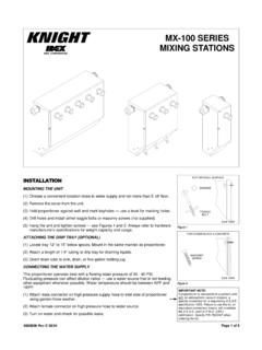
5 The signal-input circuit accepts input voltages from 14-240 VAC. The KTM-600 board also has a Relay Mode feature that allows the pump to run from a 14 240V signal (for as long as the signal is present) or while the push button is held down. Using the relay mode with the push button is well suited for manual feed applications. CT-600 This pump Cycle Timer triggers a continuous On-Off feed cycle anytime power is applied to the power input. For continuous chemical applications such as conveyor or track lubrication, the CT-600 Cycle Timer will feed from 0-12 minutes of ON time, with an OFF time from 0-63 minutes. 0900381 Rev: G (10/12) Page 3 of 12. INSTALLATION. (1) Check voltage of installation with a voltmeter and compare with voltage inputs of pump unit before mounting. Application of incorrect voltage will permanently damage unit and is not covered under warranty. (2) Mount unit on wall or shelf in a convenient location near both injection point and chemical supply. Do not mount unit in direct path of steam.
6 This can short circuit and permanently damage your system. (3) Install power leads. Most systems include a power cord for easy connection. Variable speed systems have an internal transformer which steps down the incoming voltage. Rigid or flexible conduit should be used to ensure safety and continued operation without shorts. The green ground wire must be applied to ground. Failure to do so will void warranty. (4) 500 Series: Install poly tubing between the discharge (right) tube side of the peristaltic pump and the injection point. Use tie wraps to secure flow tubing to squeeze tube. Bulkhead fittings and in-line injection fittings can be provided for various installations. 800/900 Series: Install braided tubing between the discharge (right) tube side of the peristaltic pump and the injection point. Use the provided stainless steel hose clamps and barb fittings to secure braided tubing to squeeze tube. (5) 500 Series: Install poly tubing between the suction (left) tube side and the PVC product pickup tube provided.
7 Use tie wraps to secure flow tubing to squeeze tube. Be sure to draw the tubing through the end of the pickup tube. 800/900 Series: Install braided tubing between the suction (left) tube side and the barb fitting on the PVC pickup tube provided. Use the provided stainless steel hose clamps and barb fittings to secure braided tubing to squeeze tube. (6) Some units are equipped with an optional prime switch which can be used to fill the suction and discharge tubing connected to the pump. Depending on the model, the pump will either run as long as the prime switch is depressed, or will trigger a timed injection set on the control circuit board (if so equipped). MAINTENANCE. The PMP Series of Metering Pumps require a minimal amount of maintenance to achieve optimal performance. Periodically check the squeeze tube for cracks, deterioration, or swelling. The squeeze tube will typically need to be replaced about every 6 months (chemical compatibility and duty cycle can cause this interval to vary).
8 Applying lube to the squeeze tube once a month will extend the life of the tube, minimize wear on other contacting parts, and promote smoother pump operation. Use Knight Tube Lube (P/N 7506621) or an equivalent silicone-based lubricant. (1) Remove the faceplate of the pump. (2) Apply a thin bead of Tube Lube to the inner surface (the side that the rollers contact) of the squeeze tube between the 9 o'clock and 3 o'clock positions. Avoid getting lube near the pinch points where the bottom of the faceplate grips the tube. (3) Put the faceplate back on the pump. (4) Activate the pump under normal operation the lubricant will be evenly distributed as the pump rotates. Page 4 of 12 0900381 Rev: G (10/12). MODELS WITH KTM-600. Pump Run Time: (max run time is 12 minutes and 42 seconds). (1) Locate the dip-switch pack on the circuit board set switch #6 to SIGNAL, set switch #7 to RUN TIME and set switch #8 to PROGRAM MODE. (2) Using a measuring cup or beaker, press Start switch and release when pump starts.
9 Let the pump run until desired amount of chemical is dispensed then press Start switch again to stop. The run time is now programmed. Repeat step if new volume is required. (3) Set mode switch #8 to RUN MODE. Delay Time: (max delay time is 12 minutes and 42 seconds). (1) Locate the dip-switch pack on the circuit board set switch #6 to SIGNAL, set switch #7 to DELAY TIME and set switch #8 to PROGRAM MODE. (2) Press Start switch and release when the LED begins flashing. When the desired delay time has passed, press the Start switch again. The delay time is now programmed. Repeat step if new delay time is required. (3) Set mode switch #8 to RUN MODE. Lock-Out Time: (max lock-out time is 31 minutes). This feature defeats consecutive dispensing of product for a pre-determined interval. Select a combination of switches 1 5 to program total lock-out time. Example: For 10 minute lock-out, set switches #2 and #4 to ON with all other switches OFF. For maximum lock-out (31 min) set all switches ON.
10 For no lock-out, set all switches OFF. OPERATION. Manual activation: Press the Start button for 1 full second. The unit will begin counting down the delay time (if used). and will then run the pump for the amount of time programmed. Once the lock-out time expires (if used) the pump will be ready to restart. Signal activation: When the signal input on the circuit board receives a 14-240 VAC trigger signal for at least 5. seconds, the delay time (if used) will begin counting down. Then the pump will run for the amount of time programmed. Once the lock-out time expires (if used) the pump will be ready to restart. Relay Mode: Set switch #6 to RELAY. The pump will activate for as long as an external trigger signal is present, or for as long as the manual button is depressed. All other board functions (such as delay time and lock-out time) are by -passed in relay mode. DISABLING THE START BUTTON. There is a jumper marked JP1 on the circuit board that can be used to prevent manual activation in certain applications, or to allow manual activation by remote push-button only.