Transcription of Ultra Micro-Pro UMP 100 / 200 Series Instruction …
1 Page 1 of 12 0901082 Rev: D (08/08) Ultra Micro-Pro UMP 100 / 200 Series Instruction manual 0901082 Rev: D (08/08) Page 2 of 12 TABLE OF CONTENTS Declaration of Conformity ..3 Circuit Board Probe Electrical ..6 Rinse Probe Probeless Operation ..9 Wiring Diagram ..10 Assembly Warranty Information ..12 Knight Locations ..12 EQUIPMENT RATINGS This includes equipment supply, description of I/O connections, duty cycle and operating environmental conditions. Pollution degree 2; Installation category 2; Altitude 2000 m; Humidity 50% to 80% Electrical supply 120, 208, or 240 Vac, 50/60 Hz; Indoor use statement; Temperature 5 C to 40 C; Statement advising that mains supply voltage fluctuations are not to exceed 10 percent of the nominal supply voltage.
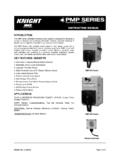
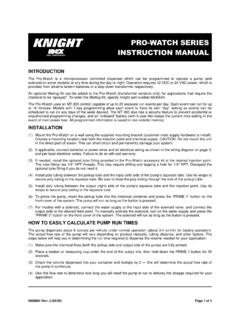
2 CAUTION: Wear protective clothing and eyewear when dispensing chemicals or other materials. Observe safety handling instructions (MSDS) of chemical mfrs. CAUTION: To avoid severe or fatal shock, always disconnect main power when servicing the unit. CAUTION: When installing any equipment, ensure that all national and local safety, electrical, and plumbing codes are met. Page 3 of 12 0901082 Rev: D (08/08) 0901082 Rev: D (08/08) Page 4 of 12 INTRODUCTION Ultra Micro-Pro UMP- Series warewash systems provide the versatility of probe or probeless detergent control through advanced microprocessor design. With the capability of controlling up to two products, and the choice of liquid or dry detergent, virtually any warewash application can be accommodated. The UMP Series warewash control features simplicity and versatility.
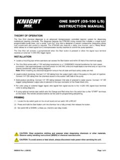
3 SLIDE SWITCH SETTINGS Probe/Probeless Switch: Allows you to select operation with or without a probe Door/Conveyor Switch: Sets alarm delay range for probe mode. Sets initial charge timing range for probeless mode. Low/High Range Switch: Used if operating in probe mode. Selects concentration ranges. Low/High Audio Switch: Sets the alarm volume. On/Off Rinse Limit Switch: When on, stops the rinse pump after 30 seconds. POTENTIOMETER SETTINGS Concentration or Recharge Pot: In probe mode sets detergent concentration strength. In probeless mode sets the pump time necessary to recharge the detergent concentration. Alarm Delay or Initial Charge Pot: In probe mode sets the time before the alarm sounds if the probe senses low detergent concentration.
4 In probeless mode sets the pump time necessary to initially charge the detergent concentration. Rinse Speed Pot: Adjust the speed at which the rinse pump runs. Rinse Delay Pot: Delays the rinse pump from 0 to 14 seconds. CONCENTRATION OR RECHARGE ALARM DELAY OR INITIAL CHARGE RINSE SPEED RINSE DELAY Page 5 of 12 0901082 Rev: D (08/08) INSTALLATION Mount the unit (using suitable hardware) with the provided bracket in the accessory kit. Try to keep the unit within three feet from the final rinse line to avoid long tubing runs. CAUTION: Do not mount the unit in the direct path of steam. This can short circuit and permanently damage the unit. Mounting the unit on the side, on the back, or on the vents of the dishwasher may cause thermal overload and damage or hinder the performance of the unit.
5 Check all applicable plumbing and electrical codes before proceeding with the installation. This will help to ensure that the system is installed in safe and suitable manner. A wiring schematic of the dishwasher should be used as reference for making electrical connections this is typically provided by the dishwasher manufacturer if one cannot be located on the machine itself. PLUMBING RINSE PLUMBING (1) Install the provided 1/4" tube x 1/8" NPT injection fitting into the side or bottom of the dishwasher rinse line between the rinse solenoid valves and the rinse jets. If necessary, drill a 11/32" hole and tap to 1/8" NPT. Use of a saddle clamp may be desired on copper rinse line for better support. (2) Cut a suitable length of 1/4" OD poly tubing and connect between the discharge (right) side of the rinse pump s squeeze tube and the injection fitting.
6 (3) Cut a suitable length of 1/4" OD poly tubing and connect between the suction (left) side of the rinse pump s squeeze tube and the pickup tube provided. Be sure to draw tubing through the end of the pickup tube. (4) Hand-tighten the compression nuts on both the rinse fitting and pickup tube. Plastic ties can be used to cinch around the connections where the poly tubing is inserted into the pump s squeeze tube. PRESSURE SWITCH PLUMBING (optional) Install pressure switch kit. Thread the male end of the tee fitting into the rinse line on the dishwasher, and connect the poly tubing from the rinse pump into the end opposite the male threads, using the checkvalve provided. Thread the pressure switch into the remaining opening on the tee, perpendicular to the male threaded end.
7 LIQUID DETERGENT PLUMBING (1) Install the provided bulkhead fitting through a wall of the wash tank (above water level). If an existing mounting hole cannot be located, use of a 7/8" hole saw or punch may be desired. (2) Cut a suitable length of 1/4" OD poly tubing and connect between the discharge (right) side of the detergent pump s squeeze tube and the bulkhead fitting. (3) Cut a suitable length of 1/4" OD poly tubing and connect between the suction (left) side of the detergent pump s squeeze tube and the pickup tube provided. Be sure to draw tubing through the end of the pickup tube. (4) Hand-tighten the compression nuts on both the bulkhead fitting and pickup tube. Plastic ties can be used to cinch around the connections where the poly tubing is inserted into the pump s squeeze tube.
8 DRY DETERGENT PLUMBING (1) A powder or solid type feeder (not provided) should be used for dispensing dry detergent products. Follow the instructions included with the detergent feeder for installation, and recommended water temperature/pressure. (2) Cut a suitable length of 1/4" OD copper tubing (not provided) and connect between the input side of the water solenoid and the water source. Maximum recommended water temperature is 140 F (60 C). (3) Cut a suitable length of 1/4" OD copper tubing (not provided) and connect between the output of water solenoid to a powder or solid detergent feeder. (4) Carefully tighten the compression nuts on the water solenoid over tightening may cause solenoid to leak. Tighten connections to the water source and detergent feeder as needed.
9 0901082 Rev: D (08/08) Page 6 of 12 PROBE INSTALLATION (if required) (1) Install the probe in the wash tank below the water level. It should be away from incoming water supplies, near the recirculating pump intake, and 3 to 4 inches from corners, heating elements, or the bottom of the tank. If an existing mounting hole cannot be located, use of a 7/8" hole saw or punch may be desired. (2) Connect leads from the terminals on the probe to the probe terminals on the circuit board. (3) For best results, use 18 AWG multi-stranded copper wire for the probe connection. Avoid running the wire near high voltage AC lines. ELECTRICAL Turn off all power before wiring the control. Check with a voltmeter to ensure power is off. MAIN POWER CONNECTION One step-down transformer is provided with the UMP control.
10 Connect the high voltage side, through a switch or circuit breaker in close proximity to the equipment and marked UMP, to any 115/208/230 VAC power source that is on when the dishmachine is on ( mains switch on dishmachine). NOTE: The transformer provides power to both the detergent and rinse circuits. The UMP will only operate detergent or rinse when electrically signaled. To wire main power connection: (1) Check the voltage of the main power source and make sure that it matches one of the three available input voltages (115/208/230 VAC) of the transformer inside the Ultra Micro-Pro . (2) Remove all power from the dishwasher. (3) Connect leads from the main power source to the appropriate wires on the transformer. * CAUTION: The UMP unit has high voltage connected to the transformer.