Transcription of Introduction to Capacitor Technologies - KEMET
1 Introduction to Capacitor Technologies What is a Capacitor ? 2013 Copyright 2013 KEMET Corporation Page 2 Table of Contents Introduction .. 3 Capacitor Construction, Parameters and Properties .. 3 Capacitor Construction .. 3 Capacitor Parameters .. 4 Dielectric Characteristics and Capacitor 6 Capacitor Properties .. 6 A Capacitor Water Tank Analogy .. 6 Practical Capacitance .. 7 Leakage Current vs. Insulation Resistance .. 7 Charge/Discharge Behavior .. 8 Dielectric Strength .. 9 Dissipation of Energy .. 9 Inductance .. 10 Equivalent Circuit Description of the Capacitor .. 11 Capacitor Technologies .. 12 Uses of capacitors .. 13 Decoupling .. 13 Filtering .. 13 Coupling .. 13 Timing and Waveshaping .. 14 Oscillators .. 14 Overview of Major Capacitor Applications .. 14 Summary: Capacitor Selection for Performance and Quality .. 15 Glossary of Terms .. 15 More about KEMET .. 16 Copyright 2013 KEMET Corporation Page 3 Introduction capacitors are electronic components that store, filter and regulate electrical energy and current flow and are one of the essential passive components used in circuit boards.
2 capacitors are primarily used for storing electrical charges, conducting alternating current (AC), and blocking or separating different voltages levels of direct current (DC) source. While capacitors are one type of component, there are many types of capacitors that are differentiated by the materials used in construction, each providing unique features and benefits. Understanding basic Capacitor construction and how different materials can affect their characteristics will aid in choosing the proper Capacitor for a given application. The unit of capacitance is the farad. For 1 farad of capacitance, 1 coulomb of charge is stored on the plates when 1 volt is applied: 1 farad = 1 coulomb / 1 volt 1 coulomb represents ~ 6 x 10¹⁹ electrons Capacitor Construction, Parameters and Properties Capacitor Construction All capacitors are formed with the same basic structure. Two parallel metal electrode plates are separated by a non-conductive material called the dielectric.
3 When a voltage exists between these conductive parallel plates, an electric field is present in the dielectric. This field stores energy and produces a mechanical force between the plates. Figure 1: Basic structure of a Capacitor . Copyright 2013 KEMET Corporation Page 4 Capacitor Parameters The amount of capacitance C for a parallel plate Capacitor is determined by the equation: C = * A / d Where A = plate area, d = distance between plates, and = dielectric material constant. Also note that: = relative dielectric constant x dielectric constant of vacuum = r x 0 Where: r is a plain number, 0 = x 10 -12 F/m This general formula shows that: 1. the larger the plate area, the larger the capacitance value 2. the smaller distance between the plates, the larger capacitance value 3. the larger the dielectric constant of the insulating (dielectric) material, the larger the capacitance Figure 2: Capacitance parameters.
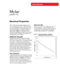
4 Copyright 2013 KEMET Corporation Page 5 Since many materials can be used as the dielectric, Figure 3 outlines the dielectric constants of some of the more commonly used materials. Dielectric Material Dielectric Constant Vacuum 1 Air Polypropylene PP Polyphenylene Sulfide PPS 3 Polyester PET Polyester PEN Impregnated Paper Mica Aluminum Oxide Tantalum Oxide Paraelectric Ceramics (Class 1) 5 90 Barium Titanate (Class 2) 3000 8000 Figure 3: Dielectric constants of commonly used materials. Taking into account the physical characteristics of the electrode plates, the distance between the plates, and the various dielectric constants, the normal ranges of values for various types of capacitors is shown in Figure 4. Figure 4: Values of capacitors by dielectric. Copyright 2013 KEMET Corporation Page 6 Dielectric Characteristics and Capacitor CV The properties of the dielectric also influence the volumetric efficiency of the Capacitor .
5 This is an important consideration when designing portable systems or very densely populated circuit boards, where high capacitance is required within small component dimensions. Volumetric efficiency is the amount of capacitance that can be provided within a given volume, and is expressed as a CV value where C is capacitance and V is voltage. A high CV is required for high volumetric efficiency. Tantalum dielectrics are known for their high CV properties. Optimizing the physical design of the Capacitor , for example by maximizing the usable electrode surface area and minimizing package overheads, also helps increase the CV of the end product. Capacitor Properties An ideal Capacitor has exactly the desired capacitance value and it is a perfect insulator. However, practical considerations must be taken into account for both the capacitance value and amount of insulation provided by a given Capacitor . 1. The Capacitor can store electric energy (as discussed earlier, the capacitance value determines the amount of charge, or energy, at given voltage) 2.
6 The Capacitor can separate different DC voltage levels from each other, but also conducts AC current 3. In general, the higher the frequency of AC voltage, the better the Capacitor conducts the AC current A Capacitor Water Tank Analogy Consider two water tanks, one larger and one smaller, connected to each other with both a pipe and a rubber membrane closing the pipe. This membrane acts like a Capacitor , separating the high water level in the larger tank (high voltage) from low water level in the smaller tank (low voltage). If there are water tight pistons resting on the water in both tanks, and one piston is moved down and up, the membrane is bending causing the other piston to move up and down. Thus, alternating movement (voltage) is transferred through the membrane ( Capacitor ) although no water (direct current) is flowing from one tank to another. The leakage current resembles a small hole in the membrane causing water to leak from higher water level tank to lower water level tank.
7 The analogy of dielectric strength is the mechanical strength of the membrane in the water pipe. Under high water pressure, the membrane can break. Copyright 2013 KEMET Corporation Page 7 Practical Capacitance While capacitors have a rated capacitance, there are a number of factors to consider in determining a Capacitor s usable capacitance. The dielectric material may cause a change in the capacitance value depending on: Temperature Humidity DC voltage AC voltage Signal frequency Age of the Capacitor Mechanical Piezoelectric effect When selecting a particular Capacitor , these proprieties must be taken into consideration. Every Capacitor is rated with a certain tolerance around its nominal value. Typically, the tolerance is coded using letters. The most common tolerance codes are: 20% = M = H 10% = K 2% = G 5% = J 1% = F The standard values used for manufacturing capacitors are based on the E-series like E6 and E12.
8 This means capacitors have nominal capacitances such as the following, E6 series: 1, , , , and and their decimal multiples (10, 15, 220, etc.) E12 series: 1, , , , , , , , , , , and their decimal multiples Leakage Current vs. Insulation Resistance The dielectric materials used in capacitors are not ideal insulators. A small DC current can flow, or leak through the dielectric material for various reasons specific to each dielectric. As a result, when a Capacitor is charged to a certain voltage, it will slowly lose its charge. As it loses its charge, the voltage between the Capacitor s electrodes will drop. The leakage current (LC) and the insulation resistance (IR) are in simple mathematical relation to each other: R (IR) = V / I (LC) or I (LC) = V / R (IR) Since the values are related, the usage of the terms leakage current and insulation resistance will vary depending on the dielectric type. Aluminum electrolytic capacitors have a relatively large leakage which is thus referred to as leakage current.
9 Alternatively, plastic film or ceramic capacitors have a very small leakage current, so the effect is quantified as an insulation resistance. Generally, insulation resistance tends to decrease with higher values of capacitance. For practical reasons the insulation resistance may be expressed in Megaohms at low capacitance values, and in Ohm-Farads (equals seconds) at higher capacitances. The Ohm-Farad expression allows a single figure to be used to describe the insulation performance of a given component family over a wide range of capacitance values. The leakage current is also dependent on the temperature. As the temperature increases, so does the leakage current. Copyright 2013 KEMET Corporation Page 8 Figure 5: Values of Capacitor types relative to dielectric Insulation Resistance (IR). Charge/Discharge Behavior When a DC voltage is applied to a Capacitor connected in series with a resistor, the Capacitor begins to charge at a rate according to the applied voltage, the state of charge relative to its final value, the series resistance, and its own capacitance.
10 The product of the resistance and capacitance is referred to as the time constant ( = R x C) of the circuit. Actually, it is the time required to charge the Capacitor by of the difference between the initial value and the final value. Hence, the value of charge plotted against time follows the curve shown in Figure 6. During this time, the charging current follows the red curve also shown in Figure 6. Figure 6. Charging a Capacitor through a series resistance. Charge on Capacitor Time Charging Current Copyright 2013 KEMET Corporation Page 9 The charge on the Capacitor at any time, t, is calculated by the following equation: Q = C x V x [1 - e-t/RC] The charging current decays according to the equation: I = V/R x e-t/RC Where e = , the so-called natural number, or the base of natural logarithm, ln(x). Many physical and even economical phenomena can be explained and described by using exponential or logarithmic functions.