Transcription of Introduction to Non-Traditional Machining
1 Introduction to Non-Traditional Machining N. SinhaDepartment of Mechanical EngineeringIIT Kanpur Email: Machining Traditional Machining is mostly based on removal of materials using tools that are harder than the materials themselves. New and novel materials because of their greatly improved chemical, mechanical and thermal properties are sometimes impossible to machine using traditional Machining processes. Traditional Machining methods are often ineffective in Machining hard materials like ceramics and composites or Machining hard materials like ceramics and composites or Machining under very tight tolerances as in micromachinedcomponents. The need to a avoid surface damage that often accompanies the stresses created by conventional Machining . Example: aerospace and electronics industries.
2 They are classified under the domain of non traditional processes. Classification of Non-Traditional MachiningThese can be classified according to the source of energy used to generate such a Machining action: mechanical, thermal, chemical and electrochemical. Mechanical:Erosion of the work material by a high velocity stream of abrasives or fluids (or both) Thermal:The thermal energy is applied to a very small portion of the work surface, causing that portion to be removed by fusion and/or vaporization of surface, causing that portion to be removed by fusion and/or vaporization of the material. The thermal energy is generated by conversion of electrical energy. Electrochemical:Mechanism is reverse of electroplating. Chemical: Most materials (metals particularly) are susceptible to chemical attack by certain acids or other etchants.
3 In chemical Machining , chemicals selectively remove material from portions of the workpart, while other portions of the surface are protected by a mask. Classification of Non-Traditional MachiningMechanical Machining Ultrasonic Machining (USM) and Waterjet Machining (WJM) are typicalexamples of single action, mechanical non traditional Machining processes. The Machining medium is solid grains suspended in an abrasive slurry in theformer, while a fluid is employed in the WJM process. The Introduction of abrasives to the fluid jet enhances themachiningefficiency and is known as abrasive water jet Machining . Similar casehappens when ice particles are introduced as in Ice Jet Machining Thermal Machining removes materials by melting or vaporizing the work piece material.
4 Many secondary phenomena occur during Machining such as microcracking, formation of microcracking, formation of heat affected zones, striations etc. The source of heat could be plasma as during EDM and PBM or photons as during LBM, electrons in EBM, ions in IBM and Electrochemical Machining Chemical milling and photochemical Machining or photochemical blanking all use a chemical dissolution action to remove the Machining allowance through ions in an ions in an etchant. Electrochemical Machining uses the electrochemical dissolution phase to remove the Machining allowance using ion transfer in an electrolytic cell. Water Jet Cutting (WJC) Also known as hydrodynamic Machining . Uses a fine, high-pressure, high-velocity of water directed at the work surface to cause cutting of the work.
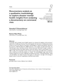
5 Nozzle diameter: to mm Pressure: up to 400 MPa Velocity: up to 900 m/s Velocity: up to 900 m/s Fluid is pressurized by a hydraulic pumpImportant process parameters Standoff distance: small to avoid dispersion of the fluid stream ( mm) Nozzle opening diameter: affects precision Water pressure: high for thicker materials Cutting feed rate: the velocity at which the WJC nozzle is traversed along the cutting path Water Jet Cutting (WJC)Water Jet Cutting (WJC) Introduction to Abrasive Jet Machining (AJM) In AJM, the material removal takes place due to impingement of the fine abrasive particles. The abrasive particles are typically of diameter and the air discharges at a pressure of several Jet Machining (AJM)Mechanics of AJM Abrasive particle impinges on the worksurface at a high velocity and this impactcauses a tiny brittle fracture and the followingair or gas carries away the dislodged smallwork piece of work surfaceFormation of cavity The process is more suitable when the work material is brittle and fragile.
6 A model for the material removal rate (MRR) is available from Sarkar and Pandey, 1980. The MRR (Q) is given as Mechanics of AJMP rocess Parameters The process characteristics can be evaluated by judging (1) the MRR, (2) the geometry of the cut, (3) the roughness of the surface produced, and (4) the rate of nozzle wear. The major parameters which control these quantities are:1. The abrasive (composition, strength, size and mass flow rate).2. The gas (composition, pressure and velocity).3. The nozzle (geometry, material, distance from and inclination to the work surface).The Abrasive Mainly two types of abrasives are used (1) Aluminum oxide and (2) Silicon carbide. (Grains with a diameter 10-50 microns are readily available) For good wear action on the surfaces, the abrasive grains should have sharp edges.
7 A reuse of the abrasive powder is normally not recommended because of a decrease of cutting capacity and clogging of the nozzle orifices due to contamination. The mass flow rate of the abrasive particles depends on the pressure and the flow rate of the mass flow rate of the abrasive particles depends on the pressure and the flow rate of the gas. There is an optimum mixing ratio (mass fraction of the abrasive in the jet) for which the metal removal rate is the highest. When the mass flow rate of the abrasive increases the material removal rate also Gas The AJM unit normally operates at a pressure of N/mm2. The composition of gas and a high velocity has a significant impact on the MRR even if the mixing ratio is not Nozzle The nozzle is one of the most vital elements controlling the process characteristics.
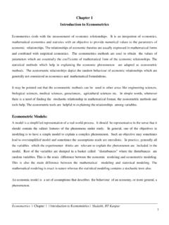
8 The nozzle material should be hard to avoid any significant wear due to the The nozzle material should be hard to avoid any significant wear due to the flowing abrasive. [Normally WC (avg. life: 12-30 hrs.) or Sapphire (Appr. = 300 hrs.) are used] For a normal operation the cross-sectional area of the orifice can be either circular or rectangular and between to Tip Distance (Stand off distance) The nozzle tip distance (NTD) or the stand off distance is a critical parameter in AJM. The NTD not only affects the MRR from the work surface but also the shape and size of the cavity produced. As shown in the figure below, when the NTD increases, the velocity of the abrasive particles impinging on the work surface increases due to their acceleration after they leave the nozzle. This increases the MRR.
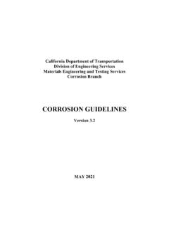
9 With a further increase in the NTD, the velocity reduces due to the drag of the atmosphere which initially checks the increase in MRR and then the atmosphere which initially checks the increase in MRR and then decreases it. Photographs of the Actual Machined Cavity Profile at Different NTDP rofile of the machined cavity at different stand off distances(a)2mm (b) 6mm (a)2mm (b) 6mm (c) 10mm (d) 14mm (e) 16mm (f) 20mmAbrasive Jet Machines The gas propulsion system supplies clean and dry gas (air, nitrogen, or CO2) to propel the abrasive particles. The gas may be supplied either by a cylinder or a compressor. In case of a compressor a filter or a dryer may be used to avoid water or oil contamination to the abrasive powder. The gas should be non toxic, cheap and easily available and should not excessively spread when discharged from nozzle into atmosphere.
10 Ultrasonic Machining (USM) Process The basic USM process involves a tool (made of a ductile and toughmaterial) vibrating with a low amplitude and very high frequency anda continuous flow of an abrasive slurry in the small gap between thetool and the work piece. The tool is gradually fed with a uniform force. The impact of the hard abrasive grains fractures the hard and brittlework surface, resulting in the removal of the work material in theform of small wear particles. Thetoolmaterialbeingtoughandductilewears outatamuch Thetoolmaterialbeingtoughandductilewears outatamuchslower Machining (USM) ProcessMechanics of USMThe reasons for material removal in an USM process are believed to be:1. The hammering of the abrasive particles on the work surface by the The impact of free abrasive particles on the work The erosion due to The chemical action associated with the fluid researchers have tried to develop the theories to predict thecharacteristics of ultrasonic Machining .