Transcription of Introduction to Vibration & Pulsation in ... - Beta Machinery
1 Pulsation / Vibration Beta Machinery Analysis 1 403-245-5666 Introduction to Vibration & Pulsation in Reciprocating Compressors Shelley D. Greenfield, Vice President, Design Services Luis de la Roche Operations Manager Beta Machinery Analysis Ltd., Calgary, AB, Canada, T3C 0J7 ABSTRACT This paper is intended to provide a basic understanding of Pulsation and Vibration in reciprocating compressor installations. Common terminology used in acoustical and mechanical analysis will also be presented. Pulsation / Vibration Beta Machinery Analysis 2 403-245-5666 Vibration Definition: The periodic movement of a body about an equilibrium position Vibration Basics Vibration amplitude is a function of an applied force and the stiffness (or flexibility) at a given frequency: Vibration = Dynamic Force = Dynamic Force X Dynamic Flexibility Dynamic Stiffness In controlling Vibration both aspects of the Vibration equation must be considered.
2 To explain Vibration , and the units it can be measured in, consider a spring-mass system. The following comments refer to Figure A block hanging on a spring will stretch the spring until the upward force of the spring equals the weight of the block. If the block is displaced down a distance ( ), and released, the spring will pull the block back to its original position. Momentum will cause the block to continue travelling upwards the same distance ( ) from the original position, where it will stop and start moving back down. The time the system takes to complete one full oscillation is the period of oscillation. The number of periods per unit of time is the frequency of the Vibration . Typical units of frequency are cycles per minute (CPM) and cycles per second (cps), which is also known as hertz (Hz). In terms of displacement, the peak-to-peak Vibration amplitude (or range of motion) is the distance travelled by the block from the highest to lowest position.
3 The peak amplitude of the Vibration is the peak to peak distance divided by two. Displacement amplitudes are typically recorded in mils (1 mil = 1/1000 inch) and must also be defined as peak or peak-to-peak. Vibration velocity is the rate at which the block moves. The velocity of the block is maximum when the block passes through the equilibrium position. The velocity is zero when the block is at the highest or lowest displacement. Velocity amplitudes are typically recorded in inch/second (ips) peak. Acceleration is the rate of change of the velocity of the block. The acceleration of the block is maximum when the velocity is zero and the block is at the highest or lowest displacement. The block acceleration is zero when the velocity is maximum, and the block passes through the equilibrium position. Typical acceleration amplitudes are recorded in g s peak (where 1 g = 386 inches per second squared).
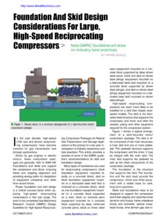
4 Pulsation / Vibration Beta Machinery Analysis 3 403-245-5666 Figure The motion of the block can be shown as displacement, velocity, or acceleration Pulsation / Vibration Beta Machinery Analysis 4 403-245-5666 Forcing Functions Reciprocating machines always generate forces that cause Vibration . Most of these forces are a function of the machine design, and cannot be avoided. Pulsation induced shaking forces are a function of operating conditions, and they can be minimized. Pulsation induced unbalanced forces are discussed in detail in Section The table below shows the forcing functions of concern in a reciprocating compressor, the frequency at which the forces are generally largest, and methods of minimizing the force, where possible. Forcing Function Dominant Frequency (Multiple of Run Speed) How to Minimize Force Mass Unbalance Mass unbalanced in opposing reciprocating components 1X, 2X Minimize opposing mass unbalance ( to 1 lbs for 1000 RPM, 6" stroke unit).
5 Moment/Couple Created by the offset of opposed reciprocating components 1X, 2X Inherent in design. Alignment Angular and parallel alignment of driver and compressor 1X, 2X Check angular and parallel alignment. Pulsation * Pulsation induced shaking forces (see Section 2). 1X, 2X, 3X, 4X, .. Control pulsations using acoustical simulation techniques. Cylinder Stretch *Elongation/shortening of cylinder assembly due to internal gas forces. 1X, 2X, 3X, 4X, .. Check that cylinder assembly bolts are properly torqued. NOTE: * - On average these forcing functions decrease with increasing multiples of runspeed. - The most significant forcing functions occur at 1X and 2X compressor run speed. In some situations, torque fluctuations can cause Vibration problems. These situations are rare and only occur when the skid is very flexible. Torque fluctuations will have input frequencies of.
6 5X, 1X, , etc. for units with four cycle engines, and 1X, 2X, 3X, etc. for units with two cycle engines or motors. Crosshead forces, caused by gas pressures and reciprocating inertia, can excite foundation modes if the foundation is resonant. Crosshead forces act perpendicular through the crosshead guide primarily at 1X and 2X. Pulsation / Vibration Beta Machinery Analysis 5 403-245-5666 Mechanical Natural Frequencies (MNFs) The mechanical natural frequency of a component is the frequency at which the component vibrates the most in response to a given force. For example, a spring-mass system will oscillate at its natural frequency if the weight is pulled down and then released. All components, or groups of components, (piping, Pulsation bottles, scrubbers, cylinders, relief valves, etc.) in a reciprocating compressor installation will have several mechanical natural frequencies.
7 The mechanical natural frequencies of a pipe or piping system depend on lengths, schedules, diameters, elbows, supports, etc. A typical mechanical natural frequency plot is shown in Figure The peak shows the frequency at which maximum dynamic flexibility (or minimum dynamic stiffness) occurs in the system. Modifications to the system will shift that peak: increasing mass or decreasing stiffness shifts the peak to the left, and increasing stiffness or decreasing mass shifts it to the right. Figure Typical Mechanical Natural Frequency Plot Resonance Mechanical resonance of a piping component occurs when a forcing function is applied at a frequency coincident with a mechanical natural frequency of the component. Figure illustrates the concept. When a system, or part of a system, is mechanically resonant, normal (or even low) unbalanced force levels can couple with the system geometry to produce very high Vibration levels.
8 If an oscillating force of constant amplitude is applied to a system over a range of frequencies, the resulting vibrations of the system will vary. Response will be high at frequencies where the system is flexible, and low elsewhere. The shape and the magnitude of the response peak at resonance is a function of the structural damping, or resistance, in the system. The more damping in the system, the broader and lower the peak will be. Structural damping comes from flanged and bolted connections, clamping, material characteristics, etc. Pulsation / Vibration Beta Machinery Analysis 6 403-245-5666 The average reciprocating compressor package, however, has very little damping. Effective damping for most components is less than 3%. At resonance, the Vibration is usually greatly amplified, sometimes by as much as a factor of 100. Therefore, the best way to avoid Vibration problems due to resonance is to avoid high dynamic flexibility (low dynamic stiffness) at the frequencies where the input forces are the greatest ( at 1X and 2X compressor speed).
9 Note: Beta Machinery Analysis field experience shows that over 90% of serious Vibration problems encountered in the field, where failures are present, are related to mechanical resonance. Figure When force frequency and natural frequency coincide, you have resonance. Pulsation / Vibration Beta Machinery Analysis 7 403-245-5666 Acceptable limits Vibration is inherent in reciprocating Machinery . Although it can be controlled, it cannot be completely eliminated. Ideally, to determine what Vibration levels are acceptable, stress levels resulting from the Vibration should be considered. When a mechanical system vibrates, it is moved from its normal or equilibrium position. Considering the top section of a piece of pipe, the Vibration alternately puts the top of the pipe in tension and compression, causing stresses in the pipe. Vibration causing large amounts of tension or compression can result in high stresses in piping, which can damage the pipe.
10 Totally eliminating all the vibrations in a given system would not be necessary or practical from a design and/or economic standpoint. However, it is necessary to reduce Vibration to a level where failure will not occur. Figure Stress in a Vibrating Pipe Pulsation / Vibration Beta Machinery Analysis 8 403-245-5666 It is much easier to measure Vibration levels than stress; therefore, Vibration limits are commonly used for defining problems. While generating Vibration criteria for every possible situation would be next to impossible, Vibration limits based on field experience have been established. Vibration limits generally considered industry standard are given in Figures and These charts give a guideline limit, as well as other limits , in displacement and velocity. The charts are presented as frequency versus Vibration amplitude. The Vibration limit charts do not distinguish between very stiff areas, such as a well supported discharge bottle, and very flexible areas, such as piping rising to coolers.