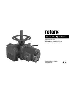
Transcription of IQ Range - Rotork
1 IQ RangeInstructions for Safe Use, Installation, Basic Setup and Maintenance This manual contains important safety information. Please ensure it is thoroughly read and understood before installing, operating or maintaining the of issue 03/182 Table of Contents1. introduction Identifying Actuator Parts .. Rotork Setting Tool .. introduction to this manual ..52. Health and Safety ATEX/IEC EX Certified Actuators ..73. Storage _____74. Operating your IQ Actuator Operating by Hand .. Operating Electrically .. Display - Local Indication.
2 Display Home screen selection .. Display Status Indication Travel .. Display Status Indication Control .. Display Alarm Indication .. Battery Alarm ..115. Preparing the Drive Bush IQ base all sizes types A and Z3 .. Non-Thrust Base Type B ..136. Mounting the Actuator Rising Stem Valves Top Mounted .. Valve with Gearbox Side Mounting .. Non-Rising Stem Valves Top Mounting .. Handwheel Sealing .. IQM Modulating Actuators .. IQL & IQML Linear Drive Unit .. IQL & IQML Adjusting Linear Stroke ..177. Cable Connections Terminal Block Layout.
3 Earth/Ground Connections.. Removing Terminal Cover .. Cable Entry .. Connecting to Terminals .. Replacing Terminal Cover ..218. Commissioning - Basic Settings Connecting to the Actuator .. Security - Password .. Basic Settings Menu .. Basic Settings Limits .. Close Settings .. Open Settings.. Torque Switch Bypass ..279. Maintenance, Monitoring and Troubleshooting _____2810. Environmental _____3011. Weights and Measures _____3112. IQ Approvals _____3213. Approved Fuses _____3414. Vibration, Shock and Noise _____3415. Conditions of Safe Use Thread details for ATEX and IECEx Approved actuators.
4 Maximum constructional flamepath gaps for ATEX and IECEx Approved actuators..35IQ3 manual Section: introduction 3 Battery sealing plugMetal (8 mm Allen key required)Plastic (10 mm Allen key required)as Identifying Actuator PartsMotorBaseTerminal CoverHand wheelOil plugControl CoverConduit entriesLocal / Remote / Stop selectorOpen / Close selectorOil plugHand / Auto leverDisplay windowName plateOil plugSide hand wheel4 IQ3 manual Section: Rotork Setting ToolThe Rotork Bluetooth Setting Tool Pro (BTST) combines the legacy IR and IrDA communication protocols with the latest Bluetooth wireless technology.
5 IR / IrDA support for older Rotork products is retained (for use as an IR communication tool, please refer to publications PUB002-003 and PUB002-004).The new BTST is able to connect to Rotork Bluetooth wireless enabled actuators and related software to setup and complete missions. Missions are configurable programs of instructions that are to be performed by the BTST on an actuator and include (but are not limited to) downloading configuration and datalogger files as well as uploading specific configurations to the actuator. Different missions can be programmed into the BTST via Insight2.
6 Rotork Bluetooth Setting Tool ProSpecificationEnclosure:Constructed in accordance with IEC 60529 to BTST has been built in accordance with the following standards:ATEX II 1 G, Ex ia IIC T4 GaIECEx Ex ia IIC T4 GaUSA FM Int Safe Class I, Div 1, Groups A, B, C & D, T4 Canada CSA Exia Int Safe, Class I, Div 1, Groups A, B, C & D, T4 Ambient Temperature Range : Tamb = -30 C to +50 COperating Range :Infra Red Bluetooth 10mEnclosure Materials:Polycarbonate ABS blend, Polycarbonate and Silicon RubberInstructions for Safe Selection, Installation, Use, Maintenance & Repair1.
7 The BTST must only be used in hazardous areas (potentially explosive atmosphere) permitted by the equipment classification, temperature class and ambient temperature Range stated above (this is also stated on the back of the BTST).2. The following checks must be conducted on the BTST prior to taking it into a hazardous area:a. The BTST function must be checked by ensuring that the red or green LED, either in the clear window or under the Enter key of the BTST, illuminates when any button is pressed. If an LED does not illuminate, there is a potential functional problem with the BTST and the inspection or battery replacement stated below in paragraph 6 must be If the BTST is likely to come in contact with aggressive substances ( solvents that may affect polymeric materials), then it is the responsibility of the user to take suitable precautions ( regular checks as part of the routine inspections or establishing that the enclosure materials are resistant to the specific chemicals)
8 That prevent the BTST being adversely affected, thus ensuring that the type of protection is not It is essential that the actuator settings are checked for compatibility with the valve, process and control system requirements before the actuator is put into No user adjustment of the BTST is The BTST must be inspected every three months, in a safe (non-hazardous), dry area by suitably trained personnel, to ensure it has been maintained in accordance with the applicable code of In accordance with the BTST hazardous area approvals and with the recommendations from the approved battery suppliers, the following are mandatory requirements for safe use:a.
9 The inspections or replacement of the batteries must be conducted in a safe (non-hazardous), dry The batteries must be removed from the BTST when it is not expected to be used for 3 months or Discharged batteries must be removed from the BTST to prevent possible The battery compartment of the BTST must be inspected every 3 months for any battery leakage. If any battery leakage has occurred then the BTST must not be manual Section: Health and Safety 5e. Only the following approved Alkaline-Manganese or Zinc-Manganese type AAA size batteries must be fitted to the BTST:- Duracell: Procell MN2400- Energizer: E92f.
10 Always replace all four batteries at the same time. Always use four unused batteries of the same approved manufacturer, type and expiry date Ensure the batteries are fitted with the correct polarity. The battery polarity (+) is indicated on the inside of the battery compartment of the The BTST contains no other user replaceable parts and it cannot be repaired by the user. If the BTST is faulty or needs repairing, it must not be introduction to this manualThis manual provides instruction on: Manual and electrical (local and remote) operation. Preparation and installation of the actuator onto the valve.