Transcription of IR SENSOR FOR TOUCHLESS MOTION AND PROXIMITY
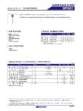
1 IS31SE5000 Integrated Silicon Solution, Inc. 1 Rev. B, 12/23/2015 IR SENSOR FOR TOUCHLESS MOTION AND PROXIMITY January 2016 GENERAL DESCRIPTION The IS31SE5000 is a low-power, reflectance-based infrared light SENSOR with advanced signal processing and digital output. The SENSOR can detect making TOUCHLESS MOTION possible. The IS31SE5000 uses one infrared LED and 2-channel receivers which pick up the reflectance signal from the 2 photodiodes to perform TOUCHLESS MOTION detection. When horizontal MOTION or PROXIMITY MOTION happen, the flag bits in status register will be triggered and an interrupt signal is generated to inform the master to read the flag bit through I2 Cinterface. IS31SE5000 is available in UTQFN-12 (2mm 2mm). It operates from to over the temperature range of -40 C to +85 C. FEATURES Supply voltage from ~ 400kHz I2C compatible interface 1 A shutdown current low supply current Detection range can be adjusted MOTION Mode and PROXIMITY Mode Integrated signal processing and digital output Auto interrupt clear Package in UTQFN-12 (2mm 2mm) APPLICATIONS Smart phones/GPS/MID/PAD/MP3 Lighting/switch controller/ household electrical appliances Toys/game machine TYPICAL APPLICATION CIRCUIT Figure 1 Typical Application Circuit ( MOTION Mode) IS31SE5000 Integrated Silicon Solution, Inc.
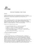
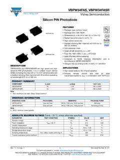
2 2 Rev. B, 12/23/2015 Figure 2 Typical Application Circuit ( PROXIMITY Mode) IS31SE5000 Integrated Silicon Solution, Inc. 3 Rev. B, 12/23/2015 PIN CONFIGURATION Package Pin Configuration (Top View) UTQFN-12 123121110987456 SDBINTBSCLSDANCRX1RX2 NCNCGNDIRLEDVCC PIN DESCRIPTION No. Pin Description 1 SDB Shutdown pin, low active. 2 INTB Interrupt signal, pulled down to inform master to read data. 3 SCL The input for the I2C clock signal. 4 SDA The input for the I2C data signal. 5,6,9 NC Not connect. 7 RX2 Input signal of channel 2 infrared LED receiver. 8 RX1 Input signal of channel 1 infrared LED receiver. 10 VCC Power supply. 11 IRLED IRLED emitting pin. Connect to IRLED. 12 GND Ground. IS31SE5000 Integrated Silicon Solution, Inc. 4 Rev. B, 12/23/2015 ORDERING INFORMATION Industrial Range: -40 C to +85 C Order Part No.
3 Package QTY/Reel IS31SE5000-UTLS2-TR UTQFN-12, Lead-free 3000 Copyright 2015 Integrated Silicon Solution, Inc. All rights reserved. ISSI reserves the right to make changes to this specification and its products at any time without notice. ISSI assumes no liability arising out of the application or use of any information, products or services described herein. Customers are advised to obtain the latest version of this device specification before relying on any published information and before placing orders for products. Integrated Silicon Solution, Inc. does not recommend the use of any of its products in life support applications where the failure or malfunction of the product can reasonably be expected to cause failure of the life support system or to significantly affect its safety or effectiveness. Products are not authorized for use in such applications unless Integrated Silicon Solution, Inc.
4 Receives written assurance to its satisfaction, that: a.) the risk of injury or damage has been minimized; b.) the user assume all such risks; and c.) potential liability of Integrated Silicon Solution, Inc is adequately protected under the circumstances IS31SE5000 Integrated Silicon Solution, Inc. 5 Rev. B, 12/23/2015 ABSOLUTE MAXIMUM RATINGS Supply voltage, VCC ~ + Voltage at any input pin ~ VCC+ Maximum junction temperature, TJMAX 150 C Operating temperature range, TA -40 C ~ +85 C Storage temperature range, TSTG -65 C ~ +150 C Thermal resistance, JA C/W ESD (HBM) ESD (CDM) 8kV 750V Note: Stresses beyond those listed under Absolute Maximum Ratings may cause permanent damage to the device.
5 These are stress ratings only and functional operation of the device at these or any other condition beyond those indicated in the operational sections of the specifications is not implied. Exposure to absolute maximum rating conditions for extended periods may affect device reliability. ELECTRICAL CHARACTERISTICS TA = 25 C, VCC = ~ , unless otherwise noted. Typical value are TA = 25 C, VCC = Symbol Parameter Condition Min. Typ. Max. Unit VCC Supply voltage V ICC Quiescent current VSDB = VCC mA ISD Shutdown current VSDB = 0V 1 3 A IIR Average current of IRLED VLED = (Note 1) mA IP Peak current of IRLED EC = 000 (Note 1, 2) 400 mA VINT INTB pin output voltage low IOL = 4mA V L Maximum detect distance EC = 000 (Note 3) 9 cm VIH Input logic high voltage VCC = V VIL Input logic low voltage VCC = V DIGITAL INPUT SWITCHING CHARACTERISTICS (NOTE 1)
6 Symbol Parameter Condition Min. Typ. Max. UnitfSCL Serial-Clock frequency 400 kHz tBUF Bus free time between a STOP and a START condition s tHD, STA Hold time (repeated) START condition s tSU, STA Repeated START condition setup time s tSU, STO STOP condition setup time s tHD, DAT Data hold time s tSU, DAT Data setup time 100 ns tLOW SCL clock low period s tHIGH SCL clock high period s tR Rise time of both SDA and SCL signals, receiving (Note 4) 20+ 300 ns tF Fall time of both SDA and SCL signals, receiving (Note 4) 20+ 300 ns Note 1: Guaranteed by design.
7 Note 2: The EC bit is used to set the emitting current. Please refer to the detailed information in Page 8. Note 3: Because of different IRLED, receive LED and material of cover, the detection distance will be different. The detail parameter should be tested. IR11-21C/TR8 (for IRLED) and PD15-22C-R/TR8 (for PD) is recommended. Note 4: Cb = total capacitance of one bus line in pF. ISINK 6mA. tR and tF measured between VCC and VCC. IS31SE5000 Integrated Silicon Solution, Inc. 6 Rev. B, 12/23/2015 DETAILED DESCRIPTION I2C INTERFACE The IS31SE5000 uses a serial bus, which conforms to the I2C protocol, to control the chip s functions with two wires: SCL and SDA. The IS31SE5000 has a 7-bit slave address (A7:A1), followed by the R/W bit, A0. Set A0 to 0 for a write command and set A0 to 1 for a read command. The complete slave address is: Table 1 Slave Address (Write only): Bit A7:A1 A0 Value 1010101 1/0 The SCL line is uni-directional.
8 The SDA line is bi-directional (open-collector) with a pull-up resistor (typically ). The maximum clock frequency specified by the I2C standard is 400kHz. In this discussion, the master is the microcontroller and the slave is the IS31SE5000. The timing diagram for the I2C is shown in Figure 3. The SDA is latched in on the stable high level of the SCL. When there is no interface activity, the SDA line should be held high. The START signal is generated by lowering the SDA signal while the SCL signal is high. The start signal will alert all devices attached to the I2C bus to check the incoming address against their own chip address. The 8-bit chip address is sent next, most significant bit first. Each address bit must be stable while the SCL level is high. After the last bit of the chip address is sent, the master checks for the IS31SE5000 s acknowledge. The master releases the SDA line high (through a pull-up resistor).
9 Then the master sends an SCL pulse. If the IS31SE5000 has received the address correctly, then it holds the SDA line low during the SCL pulse. If the SDA line is not low, then the master should send a STOP signal (discussed later) and abort the transfer. Following acknowledge of IS31SE5000, the register address byte is sent, most significant bit first. IS31SE5000 must generate another acknowledge indicating that the register address has been received. Then 8-bit of data byte are sent next, most significant bit first. Each data bit should be valid while the SCL level is stable high. After the data byte is sent, the IS31SE5000 must generate another acknowledge to indicate that the data was received. The STOP signal ends the transfer. To signal STOP , the SDA signal goes high while the SCL signal is high. READING PORT REGISTERS To read the device data, the bus master must first send the IS31SE5000 address with the R/W____ bit set to 0 , followed by the command byte, which determines which register is accessed.
10 After a restart, the bus master must then send the IS31SE5000 address with the R/W____ bit set to 1 . Data from the register defined by the command byte is then sent from the IS31SE5000 to the master (Figure 6). Figure 3 Interface timing Figure 4 Bit transfer IS31SE5000 Integrated Silicon Solution, Inc. 7 Rev. B, 12/23/2015 Figure 5 Writing to IS31SE5000 Figure 6 Reading from IS31SE5000 IS31SE5000 Integrated Silicon Solution, Inc. 8 Rev. B, 12/23/2015 REGISTERS DEFINITIONS Table 2 Register Function Address Name Function R/W Table Default 00h Status Register Store the MOTION information R 3 xxxx xxxx 01h Shutdown Register Set software shutdown W 4 0000 0000 11h Configuration Register Configure operating function W 5 Table 3 00h Status Register (Read Only) Bit D7:D4 D3:D2 D1:D0 Name - PD MD Default - The Status Register stores the MOTION information which detected by IS31SE5000.