Transcription of ispMACH 4000V/B/C/Z Family Data Sheet - Lattice Semi
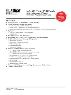
1 ispMACH 4000V/B/C/Z Family . In-System Programmable SuperFAST TM High density PLDs May 2009 Data Sheet DS1020. Features Broad Device Offering Multiple temperature range support High Performance Commercial: 0 to 90 C junction (Tj). fMAX = 400 MHz maximum operating frequency Industrial: -40 to 105 C junction (Tj). tPD = propagation delay Extended: -40 to 130 C junction (Tj). Up to four global clock pins with programmable For AEC-Q100 compliant devices, refer to clock polarity control LA- ispMACH 4000V/Z Automotive Data Sheet Up to 80 PTs per output Easy System Integration Ease of Design Superior solution for power sensitive consumer Enhanced macrocells with individual clock, applications reset, preset and clock enable controls Operation with , or LVCMOS I/O.
2 Up to four global OE controls Operation with (4000V), (4000B) or Individual local OE control per I/O pin (4000C/Z) supplies Excellent First-Time-FitTM and refit 5V tolerant I/O for LVCMOS , LVTTL, and PCI. Fast path, SpeedLockingTM Path, and wide-PT interfaces path Hot-socketing Wide input gating (36 input logic blocks) for fast Open-drain capability counters, state machines and address decoders Input pull-up, pull-down or bus-keeper Zero Power ( ispMACH 4000Z) and Low Programmable output slew rate Power ( ispMACH 4000V/B/C) PCI compatible Typical static current 10 A (4032Z) IEEE boundary scan testable Typical static current (4000C) In-System Programmable core low dynamic power (ISP ) using IEEE 1532 compliant interface ispMACH 4000Z operational down to VCC I/O pins with fast setup path Lead-free package options Table 1.
3 ispMACH 4000V/B/C Family Selection Guide ispMACH ispMACH ispMACH ispMACH ispMACH ispMACH . 4032V/B/C 4064V/B/C 4128V/B/C 4256V/B/C 4384V/B/C 4512V/B/C. Macrocells 32 64 128 256 384 512. I/O + Dedicated Inputs 30+2/32+4 30+2/32+4/ 64+10/92+4/ 64+10/96+14/ 128+4/192+4 128+4/208+4. 64+10 96+4 128+4/160+4. tPD (ns) tS (ns) tCO (ns) fMAX (MHz) 400 400 333 322 322 322. Supply Voltages (V) Pins/Package 44 TQFP 44 TQFP. 48 TQFP 48 TQFP. 100 TQFP 100 TQFP 100 TQFP. 128 TQFP. 144 TQFP1 144 TQFP1. 176 TQFP 176 TQFP 176 TQFP. 256 ftBGA2/ 256 ftBGA/ 256 ftBGA/. fpBGA2, 3 fpBGA3 fpBGA3. 1. (4000V) only. 2. 128-I/O and 160-I/O configurations. 3. Use 256 ftBGA package for all new designs. Refer to PCN#14A-07 for 256 fpBGA package discontinuance. 2009 Lattice Semiconductor Corp.
4 All Lattice trademarks, registered trademarks, patents, and disclaimers are as listed at All other brand or product names are trademarks or registered trademarks of their respective holders. The specifications and information herein are subject to change without notice. 1 Lattice Semiconductor ispMACH 4000V/B/C/Z Family Data Sheet Table 2. ispMACH 4000Z Family Selection Guide ispMACH 4032ZC ispMACH 4064ZC ispMACH 4128ZC ispMACH 4256ZC. Macrocells 32 64 128 256. I/O + Dedicated Inputs 32+4/32+4 32+4/32+12/ 64+10/96+4 64+10/96+6/. 64+10/64+10 128+4. tPD (ns) tS (ns) tCO (ns) fMAX (MHz) 267 250 220 200. Supply Voltage (V) Max. Standby Icc ( A) 20 25 35 55. Pins/Package 48 TQFP 48 TQFP. 56 csBGA 56 csBGA. 100 TQFP 100 TQFP 100 TQFP. 132 csBGA 132csBGA 132 csBGA.
5 176 TQFP. ispMACH 4000 Introduction The high performance ispMACH 4000 Family from Lattice offers a SuperFAST CPLD solution. The Family is a blend of Lattice 's two most popular architectures: the ispLSI 2000 and ispMACH 4A. Retaining the best of both families, the ispMACH 4000 architecture focuses on significant innovations to combine the highest performance with low power in a flexible CPLD Family . The ispMACH 4000 combines high speed and low power with the flexibility needed for ease of design. With its robust Global Routing Pool and Output Routing Pool, this Family delivers excellent First-Time-Fit, timing predictabil- ity, routing, pin-out retention and density migration. The ispMACH 4000 Family offers densities ranging from 32 to 512 macrocells.
6 There are multiple density -I/O com- binations in Thin Quad Flat Pack (TQFP), Chip Scale BGA (csBGA) and Fine Pitch Thin BGA (ftBGA) packages ranging from 44 to 256 pins/balls. Table 1 shows the macrocell, package and I/O options, along with other key parameters. The ispMACH 4000 Family has enhanced system integration capabilities. It supports (4000V), (4000B). and (4000C/Z) supply voltages and , and interface voltages. Additionally, inputs can be safely driven up to when an I/O bank is configured for operation, making this Family 5V tolerant. The ispMACH . 4000 also offers enhanced I/O features such as slew rate control, PCI compatibility, bus-keeper latches, pull-up resistors, pull-down resistors, open drain outputs and hot socketing. The ispMACH 4000 Family members are in-system programmable through the IEEE Standard 1532 interface.
7 IEEE Standard boundary scan testing capability also allows product testing on automated test equipment. The 1532 interface signals TCK, TMS, TDI and TDO are referenced to VCC (logic core). Overview The ispMACH 4000 devices consist of multiple 36-input, 16-macrocell Generic Logic Blocks (GLBs) interconnected by a Global Routing Pool (GRP). Output Routing Pools (ORPs) connect the GLBs to the I/O Blocks (IOBs), which contain multiple I/O cells. This architecture is shown in Figure 1. 2. Lattice Semiconductor ispMACH 4000V/B/C/Z Family Data Sheet Figure 1. functional Block Diagram CLK0/I. CLK1/I. CLK2/I. CLK3/I. VCCO0. VCCO1. GOE0. GOE1. GND. GND. GND. TMS. TDO. TCK. VCC. TDI. I/O I/O. Block 16 16 Block Generic Generic ORP 16 Logic Logic 16 ORP.
8 Global Routing Pool Block 36 36 Block I/O Bank 0. I/O Bank 1. I/O I/O. Block 16 16 Block Generic Generic ORP 16 Logic Logic 16 ORP. Block 36 36 Block The I/Os in the ispMACH 4000 are split into two banks. Each bank has a separate I/O power supply. Inputs can support a variety of standards independent of the chip or bank power supply. Outputs support the standards com- patible with the power supply provided to the bank. Support for a variety of standards helps designers implement designs in mixed voltage environments. In addition, 5V tolerant inputs are specified within an I/O bank that is con- nected to VCCO of to for LVCMOS , LVTTL and PCI interfaces. ispMACH 4000 Architecture There are a total of two GLBs in the ispMACH 4032, increasing to 32 GLBs in the ispMACH 4512.
9 Each GLB has 36 inputs. All GLB inputs come from the GRP and all outputs from the GLB are brought back into the GRP to be connected to the inputs of any other GLB on the device. Even if feedback signals return to the same GLB, they still must go through the GRP. This mechanism ensures that GLBs communicate with each other with consistent and predictable delays. The outputs from the GLB are also sent to the ORP. The ORP then sends them to the associ- ated I/O cells in the I/O block. Generic Logic Block The ispMACH 4000 GLB consists of a programmable AND array, logic allocator, 16 macrocells and a GLB clock generator. Macrocells are decoupled from the product terms through the logic allocator and the I/O pins are decou- pled from macrocells through the ORP.
10 Figure 2 illustrates the GLB. 3. Lattice Semiconductor ispMACH 4000V/B/C/Z Family Data Sheet Figure 2. Generic Logic Block To GRP. CLK0. CLK1. CLK2. CLK3. Clock Generator 1+OE. 16 MC Feedback Signals 1+OE. 1+OE. Logic Allocator 16 Macrocells 83 Product Terms To ORP. 1+OE. AND Array 36 Inputs, 36 Inputs 1+OE. from GRP. 1+OE. 1+OE. 1+OE. To Product Term Output Enable Sharing AND Array The programmable AND Array consists of 36 inputs and 83 output product terms. The 36 inputs from the GRP are used to form 72 lines in the AND Array (true and complement of the inputs). Each line in the array can be con- nected to any of the 83 output product terms via a wired-AND. Each of the 80 logic product terms feed the logic allocator with the remaining three control product terms feeding the Shared PT Clock, Shared PT Initialization and Shared PT OE.