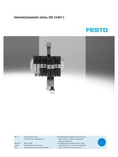
Transcription of isys H ISO Series - In-Position Technologies
1 Isys ISO Series ISO Air Control Valves 15407-2, 5599-2 & 5599-1. Sizes 18mm, 26mm, 1, 2, 3, & 4. Section L. L. Basic Valve Functions .. 2 Electrical Connections .. 26-27. Features .. 3-4 Sandwich Flow Controls .. 28. Common Part Numbers .. 5-8 Sandwich Regulators .. 29-36. Model Number Indexes .. 9-13 Technical Information .. 37-38. Manifold, Subbase Ordering Information .. 14-18 Service & Repair Kits .. 39-41. Add-A-Fold Assemblies .. 19-21 Fittings .. 42. End Plate 22 Dimensions .. 43-51. Accessories .. 23-24 Bold text part numbers are standard. Collective Wiring System .. 25 Standard text part numbers may have longer lead times.
2 Parker Hannifin Corporation Pneumatic Division Pneumatic Richland, Michigan Catalog 0600P-8/USA isys ISO Series Valves Basic Valve Functions Single Solenoid #14. 4 2. #12. Single Remote Pilot #14. 4 2. #12. 5 3. Single Pressure At Inlet Port 1: 1 Single Pressure At Inlet Port 1: 5 3. 1. De-energized position Solenoid operator #14 Normal position Pressure at inlet port 1 connected to de-energized. Pressure at inlet port 1 connected to outlet port 2. Outlet port 4 connected to exhaust port 5. outlet port 2. Outlet port 4 connected to exhaust port 5. Operated position Maintained air signal at port 14.
3 Energized position Solenoid operator #14 energized. Pressure at inlet port 1 connected to outlet port 4. Pressure at inlet port 1 connected to outlet port 4. Outlet port 2 connected to exhaust port 3. Outlet port 2 connected to exhaust port 3. Double Solenoid 4 2 Double Remote Pilot 4 2. #14 #12 #14 #12. Single Pressure At Inlet Port 1: 5 3 Single Pressure At Inlet Port 1: 5 3. 1 1. Solenoid operator #14 energized last. Pressure at inlet Momentary air signal at port 14 last. Pressure at inlet port 1 connected to outlet port 4. Outlet port 2 connected port 1 connected to outlet port 4.
4 Outlet port 2 connected to exhaust port 3. to exhaust port 3. Solenoid operator #12 energized last. Pressure at inlet Momentary air signal at port 12 last. Pressure at inlet port 1 connected to outlet port 2. Outlet port 4 connected port 1 connected to outlet port 2. Outlet port 4 connected to exhaust port 5. to exhaust port 5. APB CE APB CE. 4 2 4 2 4 2 4 2. #14 #12 #14 #12 #14 #12 #14 #12. 5 3 5 3 5 3 5 3. 1 1 1 1. Operator / Function 5 Operator / Function 6 Operator / Function 8 Operator / Function 9. PC PC. 4 2 4 2. #14 #12 #14 #12. 5 3 5 3. 1 1. Operator / Function 7 Operator / Function 0.
5 Double Solenoid Double Remote Pilot 3-Position 3-Position With #12 operator energized inlet port 1 connected to With #12 operator signaled inlet port 1 connected to cylinder port 2, cylinder port 4 connected to exhaust port 5. cylinder port 2, cylinder port 4 connected to exhaust port 5. With #14 operator energized inlet port 1 connected to With #14 operator signaled inlet port 1 connected to cylinder port 4, cylinder port 2 connected to exhaust port 3. cylinder port 4, cylinder port 2 connected to exhaust port 3. Function 5: All Ports Blocked Function 8: All Ports Blocked All ports blocked in the center position.
6 All ports blocked in the center position. Function 6: Center Exhaust Function 9: Center Exhaust Cylinder ports 2 and 4 connected to exhaust ports 3 and 5 Cylinder ports 2 and 4 connected to exhaust ports 3 and 5. in center position. Port 1 is blocked. in center position. Port 1 is blocked. Function 7: Pressure Center Function 0: Pressure Center Pressure port 1 connected to cylinder ports 2 and 4, and Pressure port 1 connected to cylinder ports 2 and 4, and exhaust ports 3 and 5 blocked in center position. exhaust ports 3 and 5 blocked in center position. Dual Pressure: May be used for dual pressure service with pressure at ports 3 & 5.
7 (Use either external pilot source option L or P or internal pilot source option E .) If pilot source E is selected, the high pressure must be at port #3. If pilot source L or P is selected, the external pilot must be plumbed to either port #14 or #12 respectively. In the 3-Position valve, the effect of dual pressure is extremely important when the valve is in the center position, as the CE and PC functions are reversed. Therefore care should be used when selecting a 3-Position valve. W ear C ompensation S ystem Maximum Performance - Low Friction - Lower Operating Pressures - Fast Response - Less Wear Long Cycle Life - Under pressure, radial expansion of the seal occurs to maintain sealing contact with the valve Non-Lube Service - No lubrication required for continuous valve shifting.
8 Bi-Directional Spool Seals - Common spool used for any pressure, including vacuum. 2 Parker Hannifin Corporation Pneumatic Division Pneumatic Richland, Michigan Catalog 0600P-8/USA (Revised 10/12/05) isys ISO Series Valves Features 15407-2 Size 01 & 02. 15407-2. Specifications HB HB: Cv (18mm). HA HA: Cv (26mm). Materials of Construction 14 5 3 12. End Caps: PBT 1. 2. Fasteners: Zinc Plated Steel Valve Body: Die Cast Aluminum Coils: Thermoset Plastic 4. Operating Pressure 4 1 2. Vacuum to 145 PSIG 15407-2 18mm Single Solenoid Energized Minimum Operating Pressure Internal Pilot 2-Position: 20 PSI Manifold Mounted 3-Position: 30 PSI.
9 L. Ports NPT and BSPP G Standard Manifolds Terminal Block Wiring (HA Only). Collective Wiring 25-Pin, D-Sub 19-Pin Round 16 Point Terminal Strip M23, 12-Pin isysnet Field Bus 12. 14. 5 3. 1. Certification / Approval 2. Approved to be CE Marked CSA / C-US Approved NEMA 4 4. IP65. 4 1 2. Manifold and Subbase Ports Meet ISO 1179 Specifications 15407-2 26mm Double Solenoid 12 End Energized External Pilot Solenoids Manifold Mounted Bi-Polar Surge Suppression (Standard). Low Watt , 24 VDC, , 120 VAC. Pressure Exhaust Indicator Lights 3 Parker Hannifin Corporation Pneumatic Division Pneumatic Richland, Michigan Catalog 0600P-8/USA (Revised 08/01/05) isys ISO Series Valves Features 5599-2 & 5599-1 Size 1, 2 & 3.
10 5599-2 5599-1. Specifications H1 H1: Cv H2 H2: Cv 12. H3 H3: Cv 14. 1 2. Materials of Construction 5. 3. 4. End Caps: PBT. Fasteners: Zinc Plated Steel H1 5599-2 Single Solenoid De-Energized Valve Body: Die Cast Aluminum Internal Pilot Coils: Thermoset Plastic Manifold Mounted Operating Pressure Vacuum to 145 PSIG. Minimum Operating Pressure 2-Position: 25 PSI. 3-Position: 30 PSI. Ports NPT and BSPP G 14 12. 2. Manifolds 5. Flying Leads 1 3. 4. Terminal Block Wiring Collective Wiring H2 5599-2 Double Solenoid 12 End Energized 25-Pin, D-Sub External Pilot 19-Pin Round Manifold Mounted M23, 12-Pin isysnet Field Bus Certification / Approval Approved to be CE Marked CSA / C-US Approved NEMA 4.


