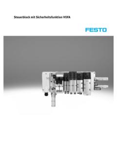
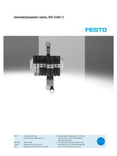
Transcription of Solenoid valves VUVG/valve terminals VTUG - Festo
1 Solenoid valves VUVG/valve terminals VTUGq/wFesto core product rangeCovers 80% of your automation tasksWorldwide:Always in stockSuperb: Festo quality at an attractive priceEasy:Reduces procurement and storing complexityqGenerally ready for shipping ex works in 24 hoursHeld in stock in 13 service centres worldwideMore than 2200 productwGenerally ready for shipping ex works in 5 daysAssembled for you in 4 service centres worldwideUp to 6 x 10¹² variants per product seriesLook for the star!Subject to change 2018/102 Internet: valves VUVGKey featuresInnovativeFlexibleReliableEasy to mount Can be set to internal or externalpilot air supply for manifolds withsub-base valves Maximum pressure 10 bar Design principle.
2 Piston slide with sealing ring(VUVG-LK, VUVG-BK) Piston spool with sealing cart ridge (VUVG-L, VUVG-B) Wide range of valve functions Choice of quick plug connectors In-line valves Semi in-line valves for manifold as sembly M5 and M7 in-line valves can becombined on one manifold rail Valve manifold with pressure zones IP40, IP65 Connection technology via: Electrical sub-base Sturdy and durable metal compon ents valves Manifold rails Fast troubleshooting thanks to360 LED display Convenient servicing thanks tovalves that can be replaced quicklyand easily Choice of manual override.
3 Non-de tenting, covered, non-detenting/de tenting or detenting (without ac cessories) Secure mounting on wall or H-rail Easy mounting, captive screws andseal Connection technology easy tochange via the electrical sub-base Identification holder for labellingthe valvesValve terminal configuratorDownload CAD data valve terminal configurator is avail able to help you select a suitablevalve terminal vtug . This makes itmuch easier to order the terminals vtug are ordered viaan ident. code. All valve terminals aresupplied fully assembled and indi vidually reduces assembly and installa tion time to a system for valve terminalVTUG Internet: vtug2018/10 Subject to change3 Internet: valves VUVGKey features PneumaticsIndividual valves and valve manifoldsIn-line valves as individual valveIn-line valve VUVG-LK/VUVG-LIn-line valves are designed to be usedwithout pneumatic linking.
4 All pneu matic connections are on the valveand can be equipped with fittings/tubing. The electrical connection isprovided by different electrical a special seal set is used, in-linevalves VUVG can also be mounted ona manifold rail (pneumatic linking) assemi in-line in-line valves for manifold assemblySemi in-line valve VUVG-SValve manifold vtug comprised ofsemi in-line valves VUVG-SIn the case of semi in-line valves , thesupply ports (1, 3 and 5) are connec ted to the valve by means of pneu matic linking ( sub-base).
5 The working ports (2, 4) are on thevalve. The electrical connection isprovided by different electrical valves for manifold assemblySub-base valve VUVG-BK/VUVG-BValve manifold vtug comprised ofVUVG-BK/VUVG-B sub-base valvesIn the case of sub-base valves , thesupply ports (1, 3 and 5) and theworking ports (2, 4) are connected tothe valve by means of pneumatic link ing ( sub-base). The electrical connection is providedby different electrical to change 2018/104 Internet: valves VUVGKey features PneumaticsBasic valves VUVGE lectrical sub-bases Size 10, 14 and 18 mm In-line valves and semi in-linevalves Sub-base valves 2x 3/2-way, 5/2-way and 5/3-wayvalvesH2H3 5, 12 and 24 V DC With or without holding current re duction LEDB asic valve and electrical sub-bases-H-NoteMore electrical connection boxes page 114 Cover caps for manual overrideIdentification holder Closed cover cap, covered manualoverride Slotted cover cap, non-detentingmanual override Cover.
6 Detenting manual override The identification holder is moun ted in the same way as a cover capfor manual override The hinged identification holdercovers the retaining screw and themanual override2018/10 Subject to change5 Internet: valves VUVGKey features PneumaticsManifold rail for in-line valvesManifold rail for sub-base valves For in-line valves M3, M5, M7,G1/8 and G1/4 For 2x 3/2-way, 5/2-way and5/3-way valves 2 to 10 and 12, 14, 16 valve posi tions For sub-base valves 10A, 10, 14and 18 Manifold rail with M5, M7, G1/8and G1/4 working ports For 2x 3/2-way, 5/2-way and5/3-way valves 2 to 10, 12, 14 and 16 valve posi tions The sub-base valves always haveexternal pilot air.
7 The pilot air is setvia the manifold rail. A short and along blanking plug are includedwith the manifold rail for this pur and exhaust at bothends is recommended for an optim ised flow rate in cases where mul tiple valves switch plate for vacant positionSupply plateVacant position coverFor additional air supply and exhaustvia a valve positionSeparator for pressure zonesFor creating multiple pressure zonesin a valve manifoldSubject to change 2018/106 Internet: valves VUVGKey features PneumaticsVertical pressure supply plateFor in-line valves M5/M7 and G1/81321In-line valves VUVG2 Vertical pressure supply plate3 Manifold railThe vertical pressure supply plateenables the valve to be pressurisedand exhausted two vertical pressure supplyplates are mounted one on top ofthe other, the valve can be suppliedwith compressed air and exhaustedcompletely independently of thevalve terminal ( terminal code CS).
8 CodeTypeFor in-line valvesDescriptionM5/M7G1/8 ZUVABF-L1-P3 AnnPlate with port 1 for supplying an individual operating pressureor separate exhausting (reverse operation) for a valve with ports 3 and 5 for exhausting the valve or supplying anindividual operating pressure (reverse operation) for a Subject to change7 Internet: valves VUVGKey features PneumaticsExhaust functions3223114 Flow restrictor for thread M5In-line valve, individual electrical con nection: flow restrictor can be fitted inport 1, 3, 5 and/or in port 2, valve, individual electricalconnection: flow control can be fittedin port 2, flow restrictor, self-tappingThe fixed flow restrictor can be usedto permanently set the exhaust flowrate in ducts 3 and fixed flow restrictors arescrewed into ducts 3 and 5 in themanifold see the relevant assembly in structions.
9 ValveCheck valves block the flow towardsthe valves if back pressure developsin ducts 3 and 5 in the case of a highexhaust capacity and thus preventsactuators from switching unexpec check valves are screwed intoducts 3 and 5 in the manifold see the relevant assembly in structions: It is not possible to use a checkvalve and a fixed flow restrictor(in the same duct) at the sametime. When screwing in again, use thethreads already VUVG with electrical individual connection2 Flow restrictor for thread M53 Fitting4 Fixed flow restrictor, self-tapping/check valveSubject to change 2018/108 Internet.
10 valves VUVGKey features PneumaticsCreating pressure zones and separating exhaust airCompressed air is supplied and ex hausted via the manifold rail and viasupply position of the supply plates andchannel separations can be freely se lected with the zones are created by isolat ing the internal supply ducts betweenthe manifold sub-bases by appropri ate channel zone separation can be usedfor the following ducts: Duct 1 Duct 3 Duct 5-H-Note Use a separator if the exhaust airpressures are high Use at least one supply plate/supply for each pressure zone Pressure zone separation is notpossible in duct 12/14 (pilot airsupply)Channel separationDescriptionThe pressure zones can be freely configured with the VUVG.
