Transcription of JEITA ET-7409/103
1 Prepared byPublished byTechnical Standardization Subcommittee on Surface Mount TechnologyStandard of Japan Electronic and Information Technology Industries AssociationSurface mount technology -Environmental and endurance test methodsfor solder joint of surface mount devicePart 103: Torque shear strength testEstablished in October, 2008 Japan Electronics and Information Technology Industries AssociationJEITA ET-7409/103 Chiyoda First Bldg. South Wing, 2-1, Nishikanda 3-chome, Chiyoda-ku, Tokyo, 101-0065, JapanPrinted in JapanIn case of a disagreement between the translation and the original version of the standard or technical report in Japanese, the original version will prevail. JEITA :2008 - Copyright - all reservedNo part of this publication may be reproduced or utilized in any form or by any means without permission in writing from the JEITA ET-7409/103 Standards of Japan Electronics and Information Technology Industries Association Surface mount technology - Environmental and endurance test methods for solder joint of surface mount device Part 103: Torque shear strength test Introduction The mechanical properties of the joint between a terminal to a land on a printed wiring board using lead free solder are not the same for the joint using tin-lead solder due to the difference in composing elements of the solders.
2 Thus it becomes important to test the mechanical properties of solder joints, using different solder alloys. 1 Scope The method is designed to test and evaluate the endurance of the solder joint between component terminals and lands on a substrate, by means of a torque shear type mechanical stress. This test is applicable to evaluate the effects of repeated temperature change on the strength of the solder joints between terminals and lands on a substrate. In this test method, the test specimens are mounted on a substrate by reflow soldering. The durability of the solder joint is evaluated by exposing the electronic components to a rapid change of temperature and applying a shear stress to the solder joint.
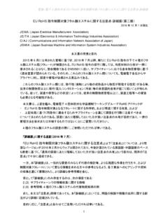
3 The exposure temperatures in this test may exceed the rated temperature range of the specific electronic component. This test is not a test to measure the strength of the electronic components. The test method to evaluate the robustness of the joint to a board is described in the following standard. JIS C 60068-2-21:2002, Environmental testing - Part 2-21: Tests - Test U: Robustness of termination and integral mounting devices Note IEC 60068-2-21:1999, Environmental testing - Part 2-21: Tests - Test U: Robustness of termination and integral mounting devices (MOD) The area of a joint to be evaluated is illustrated in Figure 1. 2 JEITA ET-7409/103 Figure 1 Area under evaluation in the shear strength test The shear strength test is applicable to most leadless surface mounting devices, except multi-leadless components (QFN, LGA etc.)
4 And gull-wing lead components to which a pull strength test is applicable. This torque shear strength test is applicable to those components to which the shear strength test is not applicable or as the product specification specifies the use of the torque shear strength. This test is applicable to those components whose length is long compared to the width, such as connectors. 2 Normative references The following referenced documents are indispensable for the application of this document. For dated reference, only the edition cited applies. For undated reference, the latest edition of the referenced document (including any amendment) applies. JEITA ET-7501/10X series standards, Land pattern design for surface mount devices (SMDs): Sectional requirements Note All the items referred in JEITA ET-7501/10X are equivalent to the items described IEC 61188-5-X, Printed boards and printed board assemblies - Design and use - Part 5-X.
5 JIS C 60068-1:1993, Environmental testing - Electricity and electronics Part 1: General and guidance Note All the clauses referred to IEC 60068-1:1988, Environmental testing Part 1: General and guidance, and Amendment 1 are equivalent to the clause in this JIS document. JIS C 60068-1: 1993 is identical to IEC 60068-1:1988. JIS C 0025:1988, Environmental testing (Electricity and electronics) - Part 2: Test N: Change of Temperature Note All the clauses referred to IEC 60068-2-14: Environmental testing - Part 2: Test N: Change of Temperature and Amendment 1:1986 and IEC 60068-2-33:1971, Environmental testing - Part 2: Tests. Guidance on change of temperature tests are equivalent to the clause in this JIS document.
6 JIS C 5603:1993, Terms and definitions for printed circuits Note All the items referred to IEC 60194-3ed are equivalent to this document. IEC 60194-4ed:1999 and IEC 60194-5ed:2006 are published, however, the corresponding JIS document is not prepared yet. Component terminal Substrate Enlarge EvaluationareaPlating layersSubstrate landIntermetallic compound layersSolder SubstrateComponent terminal 3 JEITA ET-7409/103 JIS C 6484:2005, Copper-clad laminates for printed wiring boards - Epoxide woven E-glass laminated sheet of defined flammability Note All the clauses referred to IEC 61249-2-7:2002, Materials for printed boards and other interconnecting structure - Part 2-7: Reinforced base materials clad and unclad - Epoxide woven E-glass laminated sheet of defined flammability (vertical burning test), copper-clad and IEC 61249-2-8:2003, Materials for printed boards and other interconnecting structure - Part 2-8.
7 Reinforced base materials clad and unclad - Modified brominated Epoxide woven fiberglass reinforced laminated sheets of defined flammability (vertical burning test), copper-clad are equivalent to the clause in this JIS document. IEC 61190-1-2:2007, Attachment materials for electronic assembly - Part 1-2 Requirements for solder pastes for high-quality interconnections in electronics assembly 3 Terms and definitions For the purposes of this document, the terms and definitions in JIS C 60068-1 and JIS C 5603, as well as the following, apply. torque shear strength maximum force applied to a component using a jig when a rotation moment is applied to both ends of the component in parallel to the surface of the board at the center of the component as the rotation center to break the joint of SMD mounted on aboard.
8 Displacement rate rotation speed of moving the jig, which is used to break the joint. Note radial rotation speed of the jig used in this standard (rad/s or deg/s). 4 Test equipment and materials Torque shear strength test equipment Unless otherwise specified, the torque shear strength test equipment with the following features shall be used for the torque shear test. The equipment shall have the mechanism to fasten the PWB on a base, shall be able to apply the shear force larger than the joint force between the lead of a SMD and land on the board, and shall be able to measure the torque shear strength of pushing by the side of the SMD. It is desirable that the distance between the bottom of the pushing jig and the board can be precisely controlled.
9 The accuracy of the measurement of the torque shear force shall be better than 1 % of the measured value. It is also desired that the displacement rate is within 1 % of the predetermined value. Jig for torque shear force application Unless otherwise specified, the torque shear strength test jig shall have the following properties. The jig shall have the machined rotating section as illustrated in Figure A-2 and Figure A-3 adjusted to the shape of the component to be tested in the evaluation of torque shear strength of the component. The center of the machined section is the center of the jig. The material for the jig is such as carbon steel (SK steel). 4 JEITA ET-7409/103 Optical microscope The microscope shall be able to observe an object with a magnification approximately of 50X to 250X.
10 It shall also be equipped with a lamp that can give an illumination level of approximately 2 000 lx to the object. Scanning electron microscope (SEM) The scanning electron microscope shall be able to generate a focused electron beam probe of 3 nm to 10 nm using an electric lens system and can scan over a specimen held in a vacuum chamber. The SEM shall detect secondary electrons or reflected electrons and display an enlarged image of the detected signal on a CRT or another display device. Reflow soldering oven The reflow soldering oven shall be able to realize the temperature profile given in Figure 2 in Test substrate Unless otherwise prescribed by the relevant specification, the test substrate shall be meet the following specifications.