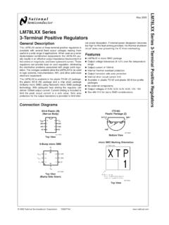
Transcription of L293, L293D QUADRUPLE HALF-H DRIVERS
1 l293 , l293 DQUADRUPLE HALF-H DRIVERS SLRS008B SEPTEMBER 1986 REVISED JUNE 20021 POST OFFICE BOX 655303 DALLAS, TEXAS 75265 DFeaturing Unitrode l293 and l293 DProducts Now From Texas InstrumentsDWide Supply-Voltage Range: V to 36 VDSeparate Input-Logic SupplyDInternal ESD ProtectionDThermal ShutdownDHigh-Noise-Immunity InputsDFunctional Replacements for SGS l293 andSGS l293 DDOutput Current 1 A Per Channel(600 mA for L293D )DPeak Output Current 2 A Per Channel( A for L293D )DOutput Clamp Diodes for InductiveTransient suppression ( L293D ) descriptionThe l293 and L293D are QUADRUPLE high-currenthalf-H DRIVERS . The l293 is designed to providebidirectional drive currents of up to 1 A at voltagesfrom V to 36 V.
2 The L293D is designed toprovide bidirectional drive currents of up to600-mA at voltages from V to 36 V. Bothdevices are designed to drive inductive loads suchas relays, solenoids, dc and bipolar steppingmotors, as well as other high-current/high-voltageloads in positive-supply inputs are TTL compatible. Each output is a complete totem-pole drive circuit, with a Darlington transistorsink and a pseudo-Darlington source. DRIVERS are enabled in pairs, with DRIVERS 1 and 2 enabled by 1,2EN anddrivers 3 and 4 enabled by 3,4EN. When an enable input is high, the associated DRIVERS are enabled and theiroutputs are active and in phase with their inputs.
3 When the enable input is low, those DRIVERS are disabled andtheir outputs are off and in the high-impedance state. With the proper data inputs, each pair of DRIVERS formsa full-H (or bridge) reversible drive suitable for solenoid or motor the l293 , external high-speed output clamp diodes should be used for inductive transient VCC1 terminal, separate from VCC2, is provided for the logic inputs to minimize device power L293and L293D are characterized for operation from 0 C to 70 2002, Texas Instruments IncorporatedPRODUCTION DATA information is current as of publication conform to specifications per the terms of Texas Instrumentsstandard warranty.
4 Production processing does not necessarily includetesting of all be aware that an important notice concerning availability, standard warranty, and use in critical applications ofTexas Instruments semiconductor products and disclaimers thereto appears at the end of this data sheet. HEAT SINK ANDGROUNDHEAT SINK ANDGROUND123456781615141312111091,2EN1A1 Y 2Y2 AVCC2 VCC14A4Y3Y3A3,4 ENN, NE PACKAGE(TOP VIEW)12345678910111213142827262524232221 2019181716151,2EN1A1 YNCNCNCNCNC2Y2 AVCC2 VCC14A4 YNCNCNCNCNC3Y3A3,4 ENDWP PACKAGE(TOP VIEW)HEAT SINK ANDGROUNDHEAT SINK ANDGROUNDL293, l293 DQUADRUPLE HALF-H DRIVERS SLRS008B SEPTEMBER 1986 REVISED JUNE 20022 POST OFFICE BOX 655303 DALLAS, TEXAS 75265block diagram103456789101112131415161210110243 MMM101010 VCVCC1 NOTE.
5 Output diodes are internal in INSTRUMENTSAVAILABLE OPTIONSPACKAGETAPLASTICDIP(NE)0 C to 70 CL293 NEL293 DNEAVAILABLE OPTIONSPACKAGED DEVICESTASMALLOUTLINE(DWP)PLASTICDIP(N)0 C to 70 CL293 DWPL293 DDWPL293NL293 DNThe DWP package is available taped and reeled. Addthe suffix TR to device type ( , l293 DWPTR). l293 , l293 DQUADRUPLE HALF-H DRIVERS SLRS008B SEPTEMBER 1986 REVISED JUNE 20023 POST OFFICE BOX 655303 DALLAS, TEXAS 75265 FUNCTION TABLE(each driver)INPUTS OUTPUTAENYHHHLHLXLZH = high level, L = low level, X = irrelevant,Z = high impedance (off) In the thermal shutdown mode, the output isin the high-impedance state, regardless ofthe input diagram 217109153611141A1,2EN2A3A3,4EN4A1Y2Y3Y4 Yschematics of inputs and outputs ( l293 )
6 InputVCC2 OutputGNDTYPICAL OF ALL OUTPUTSEQUIVALENT OF EACH INPUTVCC1 CurrentSourceGNDL293, l293 DQUADRUPLE HALF-H DRIVERS SLRS008B SEPTEMBER 1986 REVISED JUNE 20024 POST OFFICE BOX 655303 DALLAS, TEXAS 75265schematics of inputs and outputs ( L293D )InputVCC2 OutputGNDTYPICAL OF ALL OUTPUTSEQUIVALENT OF EACH INPUTVCC1 CurrentSourceGNDabsolute maximum ratings over operating free-air temperature range (unless otherwise noted) Supply voltage, VCC1 (see Note 1) 36 V.. Output supply voltage, VCC2 36 V.. Input voltage, VI 7 V.. Output voltage range, VO 3 V to VCC2 + 3 V.. Peak output current, IO (nonrepetitive, t 5 ms): l293 2 A.. Peak output current, IO (nonrepetitive, t 100 s): L293D A.
7 Continuous output current, IO: l293 1 A.. Continuous output current, IO: L293D 600 mA.. Continuous total dissipation at (or below) 25 C free-air temperature (see Notes 2 and 3) 2075 mW.. Continuous total dissipation at 80 C case temperature (see Note 3) 5000 mW.. Maximum junction temperature, TJ 150 C.. Lead temperature 1,6 mm (1/16 inch) from case for 10 seconds 260 C.. Storage temperature range, Tstg 65 C to 150 C.. Stresses beyond those listed under absolute maximum ratings may cause permanent damage to the device. These are stress ratings only, andfunctional operation of the device at these or any other conditions beyond those indicated under recommended operating conditions is notimplied.
8 Exposure to absolute-maximum-rated conditions for extended periods may affect device : 1. All voltage values are with respect to the network ground For operation above 25 C free-air temperature, derate linearly at the rate of mW/ For operation above 25 C case temperature, derate linearly at the rate of mW/ C. Due to variations in individual device electricalcharacteristics and thermal resistance, the built-in thermal overload protection may be activated at power levels slightly above orbelow the rated , l293 DQUADRUPLE HALF-H DRIVERS SLRS008B SEPTEMBER 1986 REVISED JUNE 20025 POST OFFICE BOX 655303 DALLAS, TEXAS 75265recommended operating conditionsMINMAXUNITS upply voltageVCC2 VCC136 VVIHHigh level input voltageVCC1 7 input voltageVCC1 7 output voltage free-air temperature070 C The algebraic convention, in which the least positive (most negative)
9 Designated minimum, is used in this data sheet for logic voltage characteristics, VCC1 = 5 V, VCC2 = 24 V, TA = 25 CPARAMETERTEST CONDITIONSMINTYPMAXUNITVOHHigh-level output voltageL293: IOH = 1 AL293D: IOH = AVCC2 output voltageL293: IOL = 1 AL293D: IOL = output clamp voltageL293D: IOK = AVCC2 + output clamp voltageL293D: IOK = level input currentAVI= AIIHHigh-level input currentENVI = 7 AIILLow level input currentAVI=0 3 10 AIILLow-level input currentENVI = 0 2 100 AAll outputs at high level1322 ICC1 Logic supply currentIO = 0 All outputs at low level3560mAAll outputs at high impedance824 All outputs at high level1424 ICC2 Output supply currentIO = 0 All outputs at low level26mAAll outputs at high impedance24switching characteristics, VCC1 = 5 V, VCC2 = 24 V, TA = 25 CPARAMETERTEST CONDITIONSL293NE, l293 DNEUNITPARAMETERTEST CONDITIONSMINTYPMAXUNITtPLHP ropagation delay time.
10 Low-to-high-level output from A input800nstPHLP ropagation delay time, high-to-low-level output from A inputCL=30pFSee Figure 1400nstTLHT ransition time, low-to-high-level outputCL = 30 pF, See Figure 1300nstTHLT ransition time, high-to-low-level output300nsswitching characteristics, VCC1 = 5 V, VCC2 = 24 V, TA = 25 CPARAMETERTEST CONDITIONSL293 DWP, L293NL293 DDWP, l293 DNUNITMINTYPMAXtPLHP ropagation delay time, low-to-high-level output from A input750nstPHLP ropagation delay time, high-to-low-level output from A inputCL=30pFSee Figure 1200nstTLHT ransition time, low-to-high-level outputCL = 30 pF, See Figure 1100nstTHLT ransition time, high-to-low-level output350nsL293, l293 DQUADRUPLE HALF-H DRIVERS SLRS008B SEPTEMBER 1986 REVISED JUNE 20026 POST OFFICE BOX 655303 DALLAS, TEXAS 75265 PARAMETER MEASUREMENT INFORMATIONO utputCL = 30 pF(see Note A)VCC1 Input3 VTEST CIRCUIT tftr3 V0tPHLVOHtTHLtTLHVOLTAGE WAVEFORMStPLHO utputInputVOLtwNOTES: A.