Transcription of Ladder and Functional Block Programming - Elsevier
1 CHAPTER 11 Ladder and Functional BlockProgrammingW. BoltonThis (and the following) chapter comes from the bookProgrammable logic ControllersbyW. Bolton, ISBN: 9780750681124. The first edition of the book was published in 1996,which explains why the author commences the preface by saying: Technologicaladvances in recent years have resulted in the development of the programmable logiccontroller (PLC) and a consequential revolution of control engineering. (Don t worry;the chapter presented here is from the fourth edition in 2006.)The thing is that this is something of a timeless subject, so this book provides a very usefulintroduction to programmable logic controllers and aims to ease the tasks of practicingengineers coming first into contact with programmable logic controllers. It addresses theproblem of different programmable control manufacturers using different nomenclatureand program forms by describing the principles involved and illustrating them withexamples from a range of assist the reader to develop the skills necessary to write programs for programmablelogic controllers, many worked examples, multi-choice questions and problems areincluded in the book with answers to all multi-choice questions and problems given at theend of the , programmable logic Controllers is not related to FPGAs per se, so you may bewondering why this chapter is included here.
2 The answer is simple I personally havealmost invariably found that anything I learned came in useful at some stage in my order to facilitate PLCs being used by engineers without any great knowledge ofconventional Programming languages and techniques, an approach called ladderprogramming was developed. This is a means for nonprogrammers to create can then be converted into machine code for use by the PLC method of capturing programs has been adopted by most PLC found this to be very interesting and I hope you will agree with me (see also thenext chapter in which we see examples of this technique being used in real-worldapplications). Clive Max MaxfieldPrograms for microprocessor-based systems have to be loaded into them inmachinecode, this being a sequence of binary code numbers to represent the programinstructions.
3 However,assembly languagebased on the use of mnemonics can be used;for example, LD is used to indicate the operation required to load the data thatfollows the LD, and a computer program called an assembler is used to translate themnemonics into machine code. Programming can be made even easier by the use of theso-calledhigh-level languages, such as C, BASIC, PASCAL, FORTRAN, use prepackaged functions, represented by simple words or symbols descriptiveof the function concerned. For example, with C language the symbol & is used for thelogic AND operation. However, the use of these methods to write programs requiressome skill in Programming and PLCs are intended to be used by engineers without anygreat knowledge of Programming . As a consequence, Ladder programmingwasdeveloped. This is a means of writing programs which can then be converted intomachine code by some software for use by the PLC method of writing programs became adopted by most PLC manufacturers,however each tended to have developed their own versions and so an internationalstandard has been adopted for Ladder Programming and indeed all the methods used forprogramming PLCs.
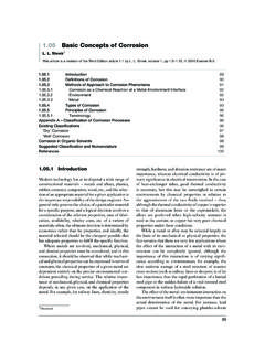
4 The standard, published in 1993, is IEC 1131-3 (InternationalElectrotechnical Commission). The IEC 1131-3 Programming languages are ladderdiagrams (LAD), instruction list (IL), sequential function charts (SFC), structuredtext (ST), and function Block diagrams (FBD).This chapter is an introduction to the Programming of a PLC using ladderdiagrams and Functional Block diagrams, with discussion of the other techniques inthe next chapter. Here we are concerned with the basic techniques involved indeveloping Ladder and function Block programs to represent basic switching operations,involving the logic functions of AND, OR, Exclusive OR, NAND and NOR, Ladder DiagramsAs an introduction to Ladder diagrams, consider the simple wiring diagram for anelectrical circuit in Figure The diagram shows the circuit for switching on or offan electric motor.
5 We can redraw this diagram in a different way, using two verticallines to represent the input power rails and stringing the rest of the circuit betweenthem. Figure shows the result. Both circuits have the switch in series with themotor and supplied with electrical power when the switch is closed. The circuit shownin Figure is termed aladder such a diagram the power supply for the circuits is always shown as two verticallines with the rest of the circuit as horizontal lines. The power lines, or rails as theyare often termed, are like the vertical sides of a Ladder with the horizontal circuit lineslike the rungs of the Ladder . The horizontal rungs show only the control portion ofthe circuit; in the case of Figure it is just the switch in series with the diagrams often show the relative physical location of the circuit components andhow they are actually wired.
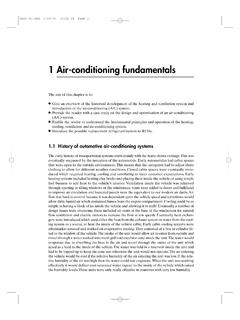
6 With Ladder diagrams no attempt is made to show the actualphysical locations and the emphasis is on clearly showing how the control is shows an example of a Ladder diagram for a circuit that is used to start andstop a motor using push buttons. In the normal state, push button 1 is open and pushbutton 2 closed. When button 1 is pressed, the motor circuit is completed and the motorstarts. Also, the holding contacts wired in parallel with the motor close and remainclosed as long as the motor is running. Thus when the push button 1 is released, theholding contacts maintain the circuit and hence the power to the motor. To stop themotor, button 2 is pressed. This disconnects the power to the motor and the holdingcontacts open. Thus when push button 2 is released, there is still no power to the we have a motor which is started by pressing button I and stopped by pressingbutton railsMotorML2L2(a)(b) inputMFigure : Ways of drawing the same electrical and Functional Block PLC Ladder ProgrammingA very commonly used method of Programming PLCs is based on the use ofladderdiagrams.
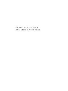
7 Writing a program is then equivalent to drawing a switching Ladder diagram consists of two vertical lines representing the power rails. Circuits areconnected as horizontal lines, , the rungs of the Ladder , between these two drawing a Ladder diagram, certain conventions are adopted:1. The vertical lines of the diagram represent the power rails between which circuits areconnected. The power flow is taken to be from the left-hand vertical across a Each rung on the Ladder defines one operation in the control A Ladder diagram is read from left to right and from top to bottom, Figure the scanning motion employed by the PLC. The top rung is read fromleft to right. Then the second rung down is read from left to right and so switchMFigure : Stop-start switchLeft power railRight power railRung 1 Rung 2 Rung 3 Rung 4 End rungPower flowENDF igure : Scanning the Ladder 11 When the PLC is in its run mode, it goes through the entire Ladder program to theend, the end rung of the program being clearly denoted, and then promptlyresumes at the start.
8 This procedure of going through all the rungs of the programis termed acycle. The end rung might be indicated by a Block with the wordEND or RET for return, since the program promptly returns to its Each rung must start with an input or inputs and must end with at least oneoutput. The term input is used for a control action, such as closing the contactsof a switch, used as an input to the PLC. The term output is used for a deviceconnected to the output of a PLC, , a Electrical devices are shown in their normal condition. Thus a switch, which isnormally open until some object closes it, is shown as open on the ladderdiagram. A switch that is normally closed is shown A particular device can appear in more than one rung of a Ladder . For example,we might have a relay that switches on one or more devices.
9 The same lettersand/or numbers are used to label the device in each The inputs and outputs are all identified by their addresses, the notation useddepending on the PLC manufacturer. This is the address of the input or outputin the memory of the shows standard IEC 1131-3 symbols that are used for input and outputdevices. Some slight variations occur between the symbols when used in semi-graphicform and when in full graphic. Note that inputs are represented by different symbolsrepresenting normally open or normally closed contacts. The action of the input isequivalent to opening or closing a switch. Output coils are represented by just one formof illustrate the drawing of the rung of a Ladder diagram, consider a situation where theenergizing of an output device, such as a motor, depends on a normally open startswitch being activated by being closed.
10 The input is thus the switch and the output themotor. Figure shows the Ladder with the input, we have the normally open symboljjfor the input contacts. Thereare no other input devices and the line terminates with the output, denoted by the symbol ( ).When the switch is closed, , there is an input, the output of the motor is while there is an input to the contacts is there an output. If there had been a normallyclosed switchj/jwith the output (Figure ), then there would have been an outputuntil that switch was opened. Only while there is no input to the contacts is there an and Functional Block Programming457In drawing Ladder diagrams the names of the associated variable or addresses of eachelement are appended to its symbol. Thus Figure shows how the Ladder diagram ofFigure would appear using (a) Mitsubishi, (b) Siemens, (c) Allen-Bradley,(d) Telemecanique notations for the addresses.