Transcription of LCP Proximal Tibial Plate 3.5. Part of the Synthes Small ...
1 LCP Proximal Tibial Plate Part of the Synthes Small Fragment LCP TechniqueThis publication is not intended for distribution in the and implants approved by the AO intensifier controlThis description alone does not provide sufficient background for direct use of DePuy Synthes products. Instruction by a surgeon experienced in handling these products is highly , Reprocessing, Care and MaintenanceFor general guidelines, function control and dismantling of multi-part instruments, as well as processing guidelines for implants, please contact your local sales representative or refer to: general information about reprocessing, care and maintenance of Synthes reusable devices, instrument trays and cases, as well as processing of Synthes non-sterile implants, please consult the Important Information leaflet (SE_023827) or refer to.
2 Proximal Tibial Plate Surgical Technique DePuy Synthes 1 IntroductionSurgical TechniqueProduct InformationMRI Information 19 Table of ContentsLCP Proximal Tibial Plate 2AO Principles 4 Indications and Contraindications 5 Implantation 6 Cleaning of Instruments 14 Implants 15 Sets 172 DePuy Synthes LCP Proximal Tibial Plate Surgical TechniqueThe LCP Proximal Tibial Plate is part of the Small Frag-ment LCP System, which merges locking screw technology with conventional plating LCP Proximal Tibial Plate has a limited-contact pro-file.
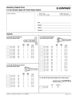
3 The head and neck portions of the Plate accept mm Stardrive or hexagonal locking screws. The screw hole pat-tern allows a raft of subchondral locking screws to buttress and maintain reduction of the articular surface. This provides resistance to local depression loads in addition to the stabil-ity of the fixed-angle construct created by locking the screws into the Locking Compression Plate (LCP) has combi-holes in the Plate shaft which combine a dynamic compression unit (DCU) hole with a locking screw hole. The combi-hole pro-vides flexibility of axial compression and locking capability throughout the length of the Plate Proximal Tibial Plate Part of the Synthes Small Fragment LCP Proximal T ibial P late Su rgical T echnique DePuy Synthes 3 Combi-holes combine a DCU hole with a threaded locking holeThree mm holes for Kirschner wires and suturesUndercuts added to Kirschner wire holes to allow for suture needle passingAccepts Articulated Tension Device (to provide compression or distraction) Proximal bend lower than standard plateElongated combi hole to aid in Plate placementAngled locking holes to support medial fragmentsFour locking screw holesStandard bend plateLow bend platePlate shaft Available with 4, 6, 8, 10, 12, 14, or 16 screw holes.
4 The three locking holes distal to the Plate head accept Locking Screw B mm (Stardrive or hexagonal) or Cortex Screw B mm or Shaft Screw B mm to secure Plate position. The hole angles allow the locking screws to converge with three of the four locking screws in the Plate head to support medial fragments. Combi-holes, distal to the three angled locking holes, combine a DCU hole with a threaded locking hole. The combi-holes accept Locking Screw B mm (Stardrive or hexagonal) or Cortex Screw B mm or Shaft Screw B mm in the threaded portion of the hole and Locking Screw B mm (Stardrive or hexagonal) or Cortex Screw B mm or Shaft Screw B mm in the DCU portion of the in left and right plates, in implant quality 316L stainless steel or pure Titanium (TiCP). Plate head Anatomically contoured to match the lateral Proximal tibia.
5 Four convergent threaded screw holes accept: Locking Screw B mm (Stardrive or hexagonal) Cortex Screw B mm Shaft Screw B mm Three mm holes for preliminary fi xation with Kirschner wires, or meniscal repair with 1 12:084 DePuy Synthes Expert Lateral Femoral Nail Surgical TechniqueAO PRINCIPLESIn 1958, the AO formulated four basic principles, which have become the guidelines for internal fixation1, M ller ME, M Allg wer, R Schneider, H Willenegger. Manual of Internal Fixation. 3rd ed. Berlin Heidelberg New York: Springer. R edi TP, RE Buckley, CG Moran. AO Principles of fracture Management. 2nd ed. Stuttgart, New York: Thieme. reductionFracture reduction and fixation to restore anatomical , active mobilizationEarly and safe mobilization and rehabilitation of the injured part and the patient as a fixationFracture fixation providing abso-lute or relative stability, as required by the patient, the injury, and the personality of the of blood supplyPreservation of the blood supply to soft tissues and bone by gentle reduction techniques and careful DePuy Synthes LCP Proximal Tibial Plate Surgical TechniqueAO Principles1 M ller ME, Allg wer M, Schneider R, Willenegger H.
6 Manual of Internal Fixation. 3rd ed. Berlin, Heidelberg, New York: Springer. 1991. 2 R edi TP, Buckley RE, Moran CG. AO Principles of fracture Management. 2nd ed. Stuttgart, New York: Thieme. fixationFracture fixation providing absolute or relative stability, as required by the patient, the injury, and the personality of the reductionFracture reduction and fixation to restore anatomical , active mobilizationEarly and safe mobilization and rehabilitation of the injured part and the patient as a of blood supplyPreservation of the blood supply to soft tissues and bone by gentle reduction techniques and careful 1958, the AO formulated four basic principles, which have become the guidelines for internal fixation1, Proximal Tibial Plate Surgical Technique DePuy Synthes 5 Indications Split-type fractures of the lateral Tibial plateau Lateral split fractures with associated depressions Pure central depression fractures Split or depression fractures of the medial plateauContraindicationsIsolated shaft.
7 For associated shaft fractures is recommended to use a stronger Plate such as the mm LCP PTP or the mm PLT/LISS plates for obese patients. In all cases an adapted reduced post-operative mobilization is manda contraindications of Norian Drillable or chronOS Inject see the corresponding surgical techniques (Norian Drillable DSEM/BIO/0515/0032, chronOS Inject DSEM/BIO/1015/0040).Indications and Contraindications6 DePuy Synthes LCP Proximal Tibial Plate Surgical Technique1 PreparationComplete the preoperative radiographic assessment and pre-pare the preoperative plan. Determine Plate length and in-struments to be used. Determine Proximal screw placement and screw lengths to ensure proper screw placement in the the patient supine on a radiolucent operating table. Visualization of the Proximal tibia under fluoroscopy in both the lateral and AP views is setA Small Fragment LCP Instrument Set is required when im-planting the LCP Proximal Tibial Plate additional sets Basic Instrument Set, for LC-DCP and DCP Small Fragment Instrument and Implant Set LC-DCP, with self-tapping screws Bone Forceps Set large distractor Set large External Fixator Set with self-drilling Schanz screws Periarticular reduction Forceps Set Pelvic Implant Set, with self-tapping screws (for longer length mm cortex screws up to 110 mm)Note: More detailed information on conventional and locked plating principles can be found in the Synthes Locking Compression Plate (LCP) surgical technique (DSEM/ TRM/0115/0278(1)).
8 Precautions: Instruments and screws may have sharp edges or moving joints that may pinch or tear user s glove or skin. Handle devices with care and dispose worn bone cutting instruments in an approved sharps container. ImplantationX-ray template for right LCP Proximal Tibial Plates (Art. No. )X-ray template for left LCP Proximal Tibial Plates (Art. No. )LCP Proximal Tibial Plate Surgical Technique DePuy Synthes 72 Reduce articular surfaceNote: Prior to reduction , application of an external fixator or large distractor ( ) may facilitate visualization and reduction of the the fracture fragments and confirm reduction using image intensification. Fragments may be reduced using inde-pendent Kirschner wires; however, Kirschner wire holes are also provided on the Plate to help achieve provisional reduc-tion, Plate position, or locking screws do not provide interfragment or Plate -to-bone compression; therefore, any desired compression must be achieved with traditional lag screws.
9 The articular frag-ments must be reduced and compression must be obtained prior to applying the LCP Proximal Tibial Plate with lock-ing : To verify that lag screws will not interfere with Plate placement, hold the Plate laterally to the bone. 3 Determine Proximal screw placementPrior to placing the Plate on the bone, thread two mm Threaded Drill Guides ( ) into two nonadjacent threaded holes in the Plate head. Insert mm Percutane-ous Drill Bits ( ) through the guides and confirm that the drill bits are parallel in the transverse plane. This verifies that the guides are properly threaded into the Plate , which ultimately ensures accurate screw DePuy Synthes LCP Proximal Tibial Plate Surgical Technique4 Determine Plate positionUsing anatomic landmarks and fluoroscopy, mount the Plate on the intact or reconstructed plateau without attempting to reduce the distal portion of the a mm Kirschner Wire ( ) through a Kirschner wire hole.
10 Readjust Plate position, if necessary. Place a second Kirschner wire in a Kirschner wire hole to prevent rotation of the Plate and to secure provisional fixa-tion of the Plate to the Tibial plateau. The Kirschner wires should penetrate and extend several milli meters beyond the medial : An additional mm Kirschner wire may be placed in the third Kirschner wire hole to hold the Plate in to proceeding, confirm Plate head placement. Use clini-cal examination and fluoroscopy to confirm that: Screw trajectories in the Proximal locking holes are paral-lel to the joint in the transverse plane, and the Plate is orientated properly on the plateau. Screw and Plate placement are consistent with the pre-operative plan. Alignment of the Plate to the shaft of the tibia is correct in both the AP and lateral views. Placement of the Plate at this point will determine final flexion/extension for Proximal screwsWhile the Plate is placed against the bone, use the mm Percutaneous Drill Bit ( ) to drill for the locking screw through one of the two threaded guides attached to the Plate .