Transcription of Lightning Protection for the Amateur Radio Station - Part 3
1 August 200253 Establishing a Good GroundNow that the SPGP (Single-Point Ground Panel) is con-nected through the wall to the outside world, there is still a lotof work to do. It s necessary to switch from brainpower andthe challenge of getting copper strap through walls to the bruteforce required to establish a good ground system. The opera-tive word here is system not a ground rod, but a network ofinterconnected ground primary purpose of the external ground system is todisperse as much of the Lightning energy as possible into theearth before it follows the feed line into the Radio Station . Nomatter how hard one tries, some of it will follow the coax,which is why you created the Protection plan for the radioequipment. The easier you make it for the strike energy todissipate in the earth before it gets to the Radio Station , theless your equipment Protection plan will be great diligence, hard work, no real estate restrictions,plenty of funds and highly conductive soil, it is possible for upto 90% of the strike energy to be dissipated in the earth, leav-ing just 10% heading for your equipment.
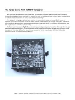
2 This would be quitean accomplishment. In many commercial sites it doesn t workout that well and rarely, if ever, for the Amateur Radio sta-tion there are always restrictions. Let s see what should bedone and then adjust to the home environment s 13 shows what has to be done. In the center, theBy Ron Block, KB2 UYTL ightning Protection forthe Amateur Radio StationPart 3 In this final installment, the author shows how to develop agood external ground system to complete your Station s 13 Aerial view of towerand equipment building showingrecommended ground radialsand perimeter ground. Tower andGround Radials drawing, The Grounds for Lightning andEMP Protection , Roger R. Block,PolyPhaser Corporation, Minden, triangles represent the tower. Ideally, the tower isseparated from the house by 20 to 50 feet. This distance pro-vides sufficient room for the dissipation of the magnetic fieldsduring the strike event.
3 This distance also takes advantage ofthe natural inductance of the antenna feed lines to limit theamount of surge and allow more time for the tower groundingsystem to absorb the strike and Ground RodsSpreading out from the base of the tower is a set of eightradials. While the number of radials required for a particularinstallation will be dependent on the soil conditions in yourlocation, the system shown here is a reasonable start. Eachradial is a bare copper wire (preferably, strap) buried 6 to 18inches below grade. The radials should be positioned so thatthe energy is dissipated away from the to the radials are ground rods. The ground rodsare spaced approximately twice the length of a ground an 8-foot rod, the spacing would be 16 feet. During thestrike, each ground rod has a cylindrically shaped region ofinfluence centered on the ground rod.
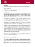
4 This is the region inwhich the ground rod disperses the strike energy. If the rodsare placed closer, the regions of influence begin to overlapand the ground rod s ability to disperse energy is this overlapping does not harm the ground system,54 August 2002 Figure 14 Grounding coaxial cablesshould be done at both the towerbase and the entry point to thehouse or building. For minimumenergy transfer from the tower, bringthe coax all the way down the towerand apply a ground kit. Coax Take-offPoint drawing, The Grounds forLightning and EMP Protection ,Roger R. Block, PolyPhaserCorporation, Minden, does increase the cost since more rods are , the connection between a radial and its ground rodshould be made using an exothermic bonding process. Thisconnection will most likely outlast the life expectancy of theground system and you won t have to do annual number of manufacturers supply the molds and fusing ma-terial for a variety of cable/strap and ground rod sizes.
5 Two ofthem are Erico Incorporated ( ) and Alltec Cor-poration ( ). If the exothermic process isnot used, mechanical clamps that can be used to connect theradial to the ground rod are available. All mechanical connec-tions must be inspected annually or more frequently to ensurethe integrity of the rods must be mechanically driven into the is the only way to ensure that the rod achieves a reason-able connection to the earth. Drilling a hole and then back-filling the space around the rod is not a very long radial/ground rod system is good, elec-trical and economic considerations come into play. Analyzingthe average cost of installing an additional foot of the ground-ing system versus the benefit of a lower impedance system, thebreak-even point is somewhere around 80 feet. For practicalpurposes in areas with reasonably conductive soil, the maxi-mum length of a radial should be limited to approximately 80feet.
6 If the impedance of the ground system needs to be lower,additional radials should be used as opposed to longer caution must be exercised when laying out the radi-als. If a radial comes within 4 feet of a metal object, it must bebonded to the metal object. The 4-foot rule applies to objectsthat are above, below, to the left or to the right of the includes metal fence posts, kids swing sets, buried fueltanks, and so on. Be sure to watch out for dissimilar metalproperties when bonding to these must be exercised when connecting the radials to thetower. Most towers are zinc-coated steel (galvanized). Con-necting a copper wire or strap directly to the tower leg willcause the zinc to erode, allowing the base steel to oxidize (rust).This in turn will increase the resistance of the connection andover time may threaten the mechanical strength of the towersegment. One solution to this problem is to use a buffer layerof stainless steel between the zinc and the copper.
7 Severalmanufacturers offer tower leg you are constructing a new tower you can use the towerbase as a ground rod. Called a Ufer ground, it utilizes therebar that reinforces the concrete base as an excellent groundconnection. The rebar itself must be electrically interconnectedso there are no spark gaps and there must be at least 4 inchesof concrete between the rebar and the surrounding earth. Ifthis is done, a wire can be brought out from the rebar and at-tached to the tower leg. A great big ground rod! No, you willnot blow up your concrete the other radials with ground rodswill handle most of the strike energy. Since you must put rebarin the concrete anyway, use it to augment your ground are two more items that need to be highlighted inFigure 13. The first is that the SPGP (or bulkhead entrancepanel) is connected to the tower ground radial system. Thisconnection should use the same material and ground rods as isused for the radials via a buried path.
8 If the distance betweenthe tower and the SPGP ground point is more than approxi-mately 100 feet, however, it may not be cost effective to inter-connect the tower ground system with the SPGP ground sys-tem. In this case some portion of the tower ground systemmust be duplicated for the SPGP ground second item is the perimeter ground, shown in Figure13 as going completely around the house or equipment build-ing. This perimeter ground serves two purposes: first, it helpsconduct the surge energy around the house, minimizing theground potential differences under the house during the strikeevent; and second, it enhances the basic ground system by pro-viding more connection points to the earth. The existing util-ity ground is also connected to the perimeter ground this isa must!Some SpecificsThat s how it should be done; here are some general guide-lines for adapting this to your specific situation.
9 In general, doubling the number of radials lowers the im-pedance of the ground system by one half. Radials don t have to go in a straight line; they can fol-low the contour of your property or flow around turns gradually (12-inch radius or larger). A perimeter ground that only goes three-quarters or half-way around the house is better than no perimeter ground atall. Although flowerbeds, walkways and driveways frequentlypresent insurmountable obstacles, do your best to get most ofthe way around. The perimeter ground must at least connectto the utility ground. Short ground rods are better than none at all. Just placethem closer together spaced at twice their length. Soil doping can improve soil conductivity. Be aware thatsome additives may cause ground and water pollution and canshorten the life of the grounding materials. Where possible when installing a new tower, place it atleast 25 feet from the house; 30 feet is even better.
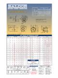
10 By placingthe tower at some distance from the house, you minimizethe amount of magnetic energy that will couple fromAugust 200255327 Barbara DrClarksboro, NJ into the wiring of the house. In addition, you take advantageof the inductance of the coax line in limiting the surge energyheaded toward your equipment. Don t get too carried away withthe distance; the added feed line also attenuates your signals. If you are fortunate enough to have multiple towers, eachshould have its own ground system of radials and ground the towers are within 100 feet of each other, a radial shouldbe used to interconnect the Cable GroundingEach coaxial cable traversing your tower needs to be prop-erly grounded to the tower. The first point is at the top of thetower where the coax connects to the antenna. The second pointis where the coax leaves the tower to go to the Radio take-off point should be as close to the base of the tower asphysically possible.