Transcription of LIQUID RING PUMP - Graham
1 LIQUID ring pumps eries 3 DesignINSTALLATION, OPERATIONANDMAINTENANCE MANUALG raham Corporation20 Florence AvenueBatavia, New York 14020(716) 343-2216, Fax (716) 343-1097e-mail: and Heat TransferGraham Corporation2 Table of ContentsSection 1 - General General Description and Principle of Description of Pump Model 2 - Installation Coupling Belt Service LIQUID Piping Shaft Seal Piping Electrical 3 - Operating Start-up Service LIQUID Shut-Down 4 - Accessory 5 - Series 3 Pump Estimated Weights (lbs.)*.. Shaft Mechanical Removal from Troubleshooting 6 - Disassembly And Reassembly Impeller End Tie Rod Torque Bearing 7 - A - Material Safety Data B - Return Material Authorization Corporation3 Section 1 - General manual will provide assistance in the set-up, operation, and maintenance of your Graham LiquidRing Pump. Please read this manual completely prior to operating your LIQUID ring Pump.
2 If you needto contact the Pump Service department for assistance, please have available the pump serial number,model number, and ID number if possible. The ID number is stamped on the edge of the dischargeflange. The Pump Service department may be reached by contacting Graham Corporation in Batavia,NY by phone (716) 343-2216, Fax (716) 343-1097, or e-mail at has an extensive stock of spare parts and replacement pumps . Stocked parts and pumps canbe shipped from our warehouse in Batavia, NY, by a carrier of your your convenience, use our toll free number ( 1-800-828-8150 ) only when ordering spare partsand replacement pumps . Please have the model number, serial number and part number of the itemsrequired when placing an order. Normal business hours are 8:00 to 5:00 ( ), Mondaythrough rebuilding service is available for pumps returned to Batavia. When a pump is returned to thefactory for repairs, please drain and flush the pump and include a Material Safety Data Sheet (MSDS)for the process in which the pump was used.
3 A Return Material Authorization (RMA) Number,issued by Graham , is required before returning a pump. A sample form is included at the back of thismanual to show what type of information is required to obtain an RMA Number. Field ServiceTechnicians are also available for travel to the jobsite for troubleshooting and repair or rebuilding document and the information contained herein are the property of Graham Corporation and mustnot be copied, in whole or in part, nor used for manufacture or otherwise disclosed without the priorwritten consent of the company. Information contained herein may, from time to time, be revisedand/or updated. Copyright Graham Corporation 1999 Graham Description and Principle of OperationGraham Vacuum pumps and Compressors are of the LIQUID ring type. Single and two stage pumps areavailable in a wide range of sizes and materials. These options are listed in the Graham Sales major component of the Graham pump is a multi-bladed rotating assembly positionedeccentrically in a cylindrical casing.
4 (See Figure 1) This assembly is driven by an external source,normally an electric motor. Service LIQUID (usually water) is introduced into the pump. As the impellerrotates, centrifugal force creates a LIQUID ring which is concentric to the casing. At the inlet, the areabetween the impeller blades (buckets) increase in size, drawing gas in. As the impeller continues torotate toward the discharge, the impeller bucket area decreases in size, compressing the gas. Thisgas, along with the LIQUID from the pump, is discharged through the outlet nozzle. The service LIQUID isseparated from the gas and cooled for reuse in the pump or sent to a drain. In addition to being thecompressing medium, the LIQUID ring performs two other important functions:1) It absorbs the heat generated by compression, friction, and condensation of theincoming ) It absorbs and washes out any process contaminants entrained in the continuous supply of service LIQUID is necessary to limit the temperature rise in the pump caused bythe heat of compression, friction, and condensation.
5 Any excessive rise in temperature will have adetrimental effect on performance, reducing the capacity and degree of vacuum attainable. Installationschematics for the supply of the service LIQUID and for the separation of the gas and LIQUID dischargedfrom the pump are shown in Section 1 ShaftSuction PortImpellerGasDischarge PortLiquid RingGas andLiquid OutletGas InletRotationGraham Corporation5 Service LIQUID quantities are a function of the particular model and the intended application. Check thedata sheet for your specific pump model or see Table 1 of Section 3 which lists typical service normal operating ranges of LIQUID ring pumps when using water at 59 F(15 C) for the service LIQUID are:Single Stage Pumpsdown to 150 mmHgATwo Stage Pumpsdown to 25 mmHgATwo Stage pumps w/Air Ejectordown to 3 mmHgASingle Stage Compressors20 psi ( bar) max. differentialTwo Stage Compressors30 psi ( bar) max. differentialThe standard materials of construction are suitable for handling air and other non-corrosive gases,while using water as the service LIQUID .
6 Other materials can be supplied for special of Pump Model CodesEach pump is designated by a model code which describes the materials of construction, size, type ofshaft seals, and any special features. An example of a typical pump is shown below. Contact Grahamfor a complete listing of the codes used to describe the of StagesFrame SizePump SeriesImpeller SizeShaft Seal CodeSpecial Features3 PV 42120 / 12 / 43 / M / NFConnectionand ShaftEnd TypePumpMaterialCodeVacuum Pump = PVCompressor = PCGraham Corporation6 Section 2 - Installation unpack the pump. Bare pumps may be lifted with a sling placed around the bearing housingsor under the slings around the motor and the pump for units supplied with C-Face motors baseplate mounted units, lift the pump-motor assemblies by the baseplate only. Do not attachslings nor hooks to the motor or the pump as this can cause misalignment. Do not attempt to run thepump until the installation work is :DO NOT RUN THE PUMP WITHOUT SERVICE LIQUID AND SHAFTSEAL Iron pumps are protected internally with a preservative solution applied at the factory beforeshipping.
7 The solution should be flushed from the pump prior to use. An MSDS form is included inthe back of this preservative solution is petroleum based and must be disposed ofin accordance with all Local, State, and Federal operation, the pump package should be carefully set, leveled, and securely bolted in place. Itis recommended that shims and grout be used as necessary under all structural members of the Series 3 pumps are supplied as a standard to accept an adapter for mounting a NEMA C-Facemotor. The pump and support bracket (adapter) should be bolted to the floor, a cement pad, orexisting framework. Level and shim as baseplates are supplied with a pump and drive motor mounted at the factory, then they should beleveled, shimmed as required, and firmly piping to the pump should be adequately supported to eliminate any stress at the pumpconnections. All piping joints should be tested for leaks prior to start-up.
8 A temporary start-up strainerin the process inlet piping may be used to keep large contaminates from entering the pump at Corporation7 The location of the installation or the storage of the pump should be in an area that willnot subject the pump to the pump s rotation direction by checking the arrow on the shaft end casing. Refer to concerning the electrical AlignmentCAUTION: TO PREVENT PERSONAL INJURY, DO NOT OPERATE THE PUMPWITHOUT PROPERLY GUARDING THE DRIVE Series 3 pumps utilize precise machining of the pump drive end bearing housing, motor adapter,and C-Face motor flange to eliminate shaft misalignment. The coupling should be inspected mounted pumps and motors supplied from the factory have had the shafts aligned prior toshipment. This ensures that alignment can be done in the field. It is required that the shaft alignmentbe rechecked after mounting on a level foundation and prior to smoother operation and longer life of the coupled equipment, the following maximum misalignmenttolerances are recommended for baseplate mounted units:The maximum allowable parallel shaft misalignment is " ( mm).
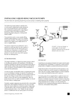
9 The maximum allowable angular shaft misalignment is " per inch( per mm) of coupling diameter. "D " x DGraham DrivesCAUTION:TO PREVENT PERSONAL INJURY, DO NOT OPERATE THEPUMP WITHOUT PROPERLY GUARDING THE DRIVE pumps are supplied with belt drives, follow the belt manufacturer s instructions to set the LIQUID Piping ArrangementsThe operating principle of a LIQUID ring pump depends on a continuous supply of clean service LIQUID ,which is normally water. The LIQUID enters the pump through a connection on the casing and isdischarged from the pump along with the gas. There are two basic piping arrangements that can beused for LIQUID ring pump applications. A once-through method with no recovery of the service liquidand a recirculation method which re-uses the service of these arrangements have four basic elements:1) A supply of service ) A means to control flow of service ) A means of stopping the flow of service LIQUID when the pump is ) A means of separating the gas / LIQUID exhaust is recommended to use a strainer to ensure that foreign matter does not enter the pump with theservice LIQUID supply or make-up source.
10 See Diagrams 1 and 2 for the proper piping : COMPLETE ALL PIPING INSTALLATION AND MAKE SURE ASUPPLY OF SERVICE LIQUID IS AVAILABLE BEFORESTARTING THE Corporation9A) Typical Installation of Once Through with No RecoveryThe service LIQUID is piped directly from a supply source to the pump. The LIQUID is separated from thegas in the separator and discharged to a drain. No recirculation nor recovery takes place. This is themost basic arrangement and can be used when service LIQUID conservation or contamination is not aconcern. A solenoid operated valve provides for flow of the LIQUID simultaneously with the pump/motoroperation. When the motor stops, the valve closes to prevent the pump casing from filling with by-pass valve is used to pre-fill the pump at initial start-up only. It also can be used should thesolenoid fail. When a manual valve is used, it must be opened immediately after starting the motor andclosed immediately before turning the motor Check ValveG-Shut-off ValveB-Pressure Gauge (vacuum gauge for vacuum service orcompound gauge for compressor service)H-J-KRegulating ValveSolenoid ValveCompound GaugeC-D-Vacuum Relief Valve (not required for compressorservice)SeparatorL-MLiquid ring PumpTrap (required if dischargepressure is above atmosphericpressure)E-By-Pass ValveF-StrainerOnce Through with No RecoveryDiagram 1 ProcessInletServiceLiquid InletGasOutletLiquidDrainSADFGHEJKCBMLG raham Corporation10B) Typical Installation of Closed Loop with Total RecoveryThis arrangement provides for the total recirculation of the service LIQUID .