Transcription of littelfuse thyristor C106 D datasheet
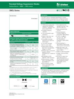
1 2020 littelfuse , are subject to change without notice. Revised: 05/01/20 ThyristorsSurface Mount > 200 - 600V > C106 Series Glassivated Surface for Reliability and Uniformity Power Rated at Economical Prices Practical Level Triggering and Holding Characteristics Flat, Rugged, Thermopad Construction for Low Thermal Resistance, High Heat Dissipation and Durability Sensitive Gate Triggering These are Pb Free DevicesFeaturesGlassivated PNPN devices designed for high volume consumer applications such as temperature, light, and speed control; process and remote control, and warning systems where reliability of operation is SeriesFunctional DiagramAdditional InformationSamplesResourcesDatasheetPin OutPbK,1G,3A,2TO-225A ACase 77 Style 2321 2020 littelfuse , are subject to change without notice. Revised: 05/01/20 ThyristorsSurface Mount > 200 - 600V > C106 SeriesRatingSymbolValueUnitPeak Repetitive Off State Voltage(Sine Wave, 50 60 Hz, RGK = 1 K,TC = 40 to 110 C)C106BC106D, C106D1*C106 MVDRM, VRRM200400600 VOn-State RMS Current (180 Conduction Angles, TC = 80 C)IT (RMS) On State Current (180 Conduction Angles, TC = 80 C)IT(AV) Non-Repetitive Surge Current(1/2 Cycle, Sine Wave, 60 Hz, TJ = +25 C)ITSM20 ACircuit Fusing Considerations (t = ms) Peak Gate Current(Pulse Width sec, TC = 80 C) Peak Gate Power (Pulse Width sec, TC = 80 C) Average Gate Power (Pulse Width sec, TC = 80 C)PG(AV) Junction Temperature RangeTJ-40 to +110 CStorage Temperature RangeTstg-40 to +150 CMounting Torque (Note 2) Ratings (TJ = 25 C unless otherwise noted)Stresses exceeding Maximum Ratings may damage the device.
2 Maximum Ratings are stress ratings only. Functional operation above the Recommended Operating Conditions is not implied. Extended exposure to stresses above the Recommended Operating Conditions may affect device VDRM and VRRM for all types can be applied on a continuous basis. Ratings apply for zero or negative gate voltage; however, positive gate voltage shall not be applied concurrent with negative potential on the anode. Blocking voltages shall not be tested with a constant current source such that the voltage ratings of the devices are Torque rating applies with use of torque washer (Shakeproof WD19523 or equivalent). Mounting Torque in excess of 6 in. lb. does not appreciably lower case-to-sink thermal resistance. Main terminal 2 and heat-sink contact pad are Characteristics RatingSymbolValueUnitThermal Resistance,Junction to Case (AC)Junction to AmbientR JCR C/WMaximum Lead Temperature for Soldering Purposes, 1/8 from case for 10 secondsTL260 CElectrical Characteristics - OFF (TJ = 25 C unless otherwise noted)Electrical Characteristics - ON (TJ = 25 C unless otherwise noted)CharacteristicSymbolMinTy pMaxUnitPeak Repetitive Forward or Reverse Blocking Current(VAK = Rated VDRM or VRRM, RGK = 1 k)TJ = 25 CIDRM, IRRM__10 A TJ = 110 C 10 0 ACharacteristicSymbolMinTy pMaxUnitPeak Forward On-State Voltage (Note 3) (ITM = 4 A)VTM Trigger Current (Continuous dc)(VD = 12 V, RL = 100 , All Quadrants)TJ = 25 CIGT_15200 A TJ = -40 C 35500 Peak Reverse Gate Voltage (IGR = 10 A)VGRM Trigger Voltage (Continuous dc)(VD = 12 Vdc, RL = 100 , TC = 25 C)
3 TJ = 25 TJ = -40 0 Gate Non Trigger Voltage (Continuous dc) (Note 4)(VAK = 12 V, RL = 100 (VAK = 12 V, RL = 100 , TJ = 110 C), TJ = 110 C) Current(VAK = 12 V, IG = 20 mA, RGK = 1 k )TJ = 25 TJ = -40 C 0 Holding Current(VD = 12 Vdc)(Initiating Current = 20 mA, RGK = 1 k )TJ = 25 TJ = -40 = +110 2020 littelfuse , are subject to change without notice. Revised: 05/01/20 ThyristorsSurface Mount > 200 - 600V > C106 SeriesDynamic CharacteristicsCharacteristicSymbolMinTy pMaxUnitCritical Rate-of-Rise of Off State Voltage (VAK = Rated VDRM, Exponential Waveform, RGK = 1k ,TJ = 110 C)dv/dt V/ s3. Pulse Test: Pulse Width ms, Duty Cycle 2%.4. RGK is not included in Current Characteristic of SCRS ymbolParameterVDRMPeak Repetitive Forward Off State VoltageIDRMPeak Forward Blocking CurrentVRRMPeak Repetitive Reverse Off State VoltageIRRMPeak Reverse Blocking CurrentVTMM aximum On State VoltageIHHolding Current+CurrentQuadrant 1 Main Terminal 2 +VTMIHOn StateOff StateIDRM at VDRM+VoltageIRRM at VRRMQ uadrant 3 Main Terminal 2 -IHVTM 2020 littelfuse , are subject to change without notice.
4 Revised: 05/01/20 ThyristorsSurface Mount > 200 - 600V > C106 SeriesFigure 1. Average Current DeratingFigure 3. Typical Gate Trigger Current vs. Junction TempFigure 5. Typical Gate Trigger Voltage vs. Junction TempFigure 2. Maximum On-State Power DissipationFigure 4. Typical Holding Current vs. Junction Temp Figure 5. Typical Latching Current vs. Junction Temp 2020 littelfuse , are subject to change without notice. Revised: 05/01/20 ThyristorsSurface Mount > 200 - 600V > C106 SeriesDimensionsPart Marking SystemPin Assignment1 Cathode2 Anode3 GateOrdering Information DevicePackageShippingC106 BGTO225AA(Pb-Free)2500 Units/BoxC106 DGC106D1G*C106 MGC106M1G*C106 MTG 60 Units/Tube1920 Units/Box*D1 signifies European equivalent for D suffix and M1 signifies European equivalent for M Notice - Information furnished is believed to be accurate and reliable. However, users should independently evaluate the suitability of and test each product selected for their own applications.
5 littelfuse products are not designed for, and may not be used in, all applications. Read complete Disclaimer Notice at DIMENSIONING AND TOLERANCING PER ANSI , CONTROLLING DIMENSION: 077-01 THRU -08 OBSOLETE, NEW STANDARD PDL1eecb2 x2LA1 APIN4 BACKSIDE TABbC106xxGYMAXXY=YearM=MonthA=Assembly SiteXX=Lot Serial CodeC106xx=Device Codexx=B, D, D1, M, M1G=Pb-Free PackageTO-225A ACase 07 7 Style 21. Cathode2. Anode3. Gat