Transcription of Low- κ Dielectrics
1 1EE311/ Low-k Dielectrics1 tanford UniversityaraswatProf. Krishna SaraswatDepartment of Electrical EngineeringStanford UniversityStanford, CA DielectricsEE311/ Low-k Dielectrics2 tanford Universityaraswat Signaling Delay Power dissipation Bandwidth Self heating Data reliability (Noise) Cross talk ISI: impedance mismatch Area Depend on R, C and L ! Function and length dictates relative importance Performance Metrics Clocking Timing uncertainty (skew and jitter) Power dissipation Slew rate Area Power Distribution Supply reliability Reliability Electromigration2EE311/ Low-k Dielectrics3 tanford UniversityaraswatInterplay Between Signaling Metrics AR increase (tradeoffs)=> Better delay and electromigration Worse power and cross talk Increasing aspect ratio may not help Pay attention to different metrics simultaneously Design window quite complex Capacitance very important2 IMDILD totintIMDtalktotint2totinttotintAR11 CCXCfVCPRC!
2 "#$%&+=''='(()*RC-DelayPowerCrosstalkHWC ILDCIMDAR=H/WM1M3M2EE311/ Low-k Dielectrics4 tanford Universityaraswat The dielectric constant, , is a physical measure of the electric polarizability of amaterial Electric polarizability is the tendency of a material to allow an externally appliedelectric field to induce electric dipoles (separated positive and negative charges)in the material. Polarization P is related to the electric field E and thedisplacement D byD = oE + P P is related to E through e the electric susceptibility of the dielectricP = o eETherefore D = o (1+ e )E = o EDielectric Constantwhere o is the permittivity of the free that P also is the density of atomic electric dipole per unit volumeP = p/V = Npwhere p is the dipole moment and N is the density of dipoles3EE311/ Low-k Dielectrics5 tanford Universityaraswat In solid state matter, there are three polarization polarization occurs in neutral atoms when an electric field displaces thenucleus with respect to the electrons that surround it.)
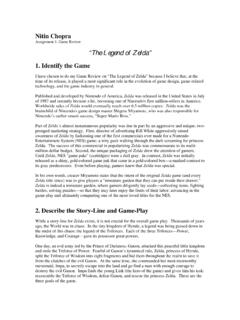
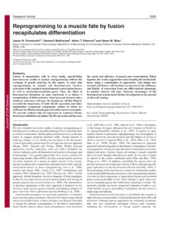
3 Example: Hydrogen atom, Si, or ionic polarization occurs when adjacent positive and negative ions stretchunder an applied electric field. Example: NaCl, most Dielectrics Compond semiconductors (GaAs, SiC have both electronic and ionic polarization) or orientational polarization occurs when permanent dipoles in asymmetricmolecules respond to the applied electric field. Example: H2 OComponents of Dielectric Polarization+ q- qE = 0 With E+ q- q+ - E = 0+ + - With EE = 0 With EEE311/ Low-k Dielectrics6 tanford Universityaraswat In a perfect vacuum, there are are no atoms to polarize, making e = 0 and k = 1. Each polarization mechanism has an associated response time and therefore will notcontribute to k beyond some corresponding frequency.
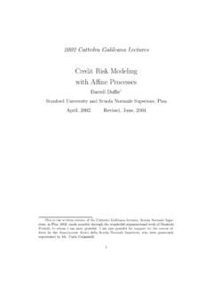
4 At the frequency of interest to us all 3 mechanisms contribute to polarization but relativecontributions may vary from material to materialComponents of Dielectric PolarizationAtomic ElectronicDipolarFrequency (Hz)Dielectric ConstantAtomicElectronic++4EE311/ Low-k Dielectrics7 tanford Universityaraswat Choose a nonpolar dielectric system. For example, polarity is weak in materialswith few polar chemical groups and with symmetry to cancel the dipoles ofchemical bonds between dissimilar atoms. Since kair = 1, Dielectrics can also have lower effective k with the incorporationof some porosity into the chemical structure. Materials where atoms are far apart (remember P = Np) Add physical porosity Minimize the moisture content in the dielectric or alternatively design a dielectricwith minimum hydrophilicity.
5 Since k water ~ 80, a low-k dielectric needs toabsorb only very small traces of water before losing its permittivity low- k dielectric is an insulating material that exhibits weak polarization whensubjected to an externally applied electric field. A few practical approaches todesign low- k materials are:Low Dielectric ConstantEE311/ Low-k Dielectrics8 tanford UniversityaraswatChallenges for Low- MaterialsWeak Thermo-Mechanical Strength: 10x worse than SiO2 inalmost every category of thermo-mechanical : Jan, IEDM Short Course, 20035EE311/ Low-k Dielectrics9 tanford Universityaraswat Reduce polarization strength and density. Reduce Si-O density: SiO2 (k=4) Incorporate F: SiOF(k = ) Incorporate CH3-: SiOC(H) (k= ) Use low polarization polymer:(Ref.)
6 : Miller et al., Macromolecules, 23, 3855 (1990).)Dielectric Constant Reduction MethodsEE311/ Low-k Dielectrics10 tanford UniversityaraswatLow Dielectric Constant (Low-k) MaterialsOxide DerivativesF-doped oxides (CVD)k = oxides (SOG, CVD)k = oxides (SOG)k = (spin-on)k = polymers (spin-on)k = parylene; parylene-Fk ~ ; k ~ amorphous carbonk = (spin-on)k = Porous OxidesXerogels/Aerogelsk = Airk = 16EE311/ Low-k Dielectrics11 tanford UniversityaraswatIndustry split between CVD and spin-on. Currently CVD dominates fork > and spin-ons dominate at k < porous films (< 65 nm).Deposition Methods CVD vs. Spin-onCVDCVD: Proven technology No cure step. Mechanical strength . Easier integration. By equipment vendorsSpin-on: Done on track.
7 Need post treatment. Mechanical strength . By materials : Jan, IEDM Short Course, 2003EE311/ Low-k Dielectrics12 tanford UniversityaraswatSiOF (F-Silicate Glass) k ~ Basic Process Chemistry:SiH4+ SiF4+O2 SiOxFy(H)z (HDP/PECVD, T> 450 C) Structure: F substitution of O in the 3D network of Si and O. Properties: k: k < and F > 4% not stable with high moisture Low-k Dielectrics13 tanford Universityaraswat CDO (Carbon Doped Oxide), OSG (Organo Silicate Glass), SiOC Proven CVD technology for 90 nm node. k ~ to with decreasing mechanical strengthCVD Organo Silicates k ~ Low-k Dielectrics14 tanford UniversityaraswatSOP (Spin-On Polymer)Spin-on Organics: k ~ : Weak mechanical strength (hardness, modulus), poorthermal stability, poor adhesion (can be improved with adhesionpromoter), high , BCBTM, ---8EE311/ Low-k Dielectrics15 tanford UniversityaraswatMechanical Strength: CVD SiOC > Spin-on SiOC > Spin-on Organics SiO2, SiOF 10x of low kAdhesion: SiO2, SiOF 10x of low k Spin-on Organic > CVD SiOC Blister, Cracking and PropertiesEE311/ Low-k Dielectrics16 tanford UniversityaraswatDielectric constants can be lowered via porosity (air = 1).
8 PoresDielectricDielectric Constants and PorosityRef: Jan, IEDM Short Course, 20039EE311/ Low-k Dielectrics17 tanford UniversityaraswatMaterial Options: Porous Silicate Glass Xerogel/Aerogel Porous Organo Silicate Glass Porous SSQ Porous Organics Porous SiLKSpin-on Sol-Gel is the most common Process: Sol: (Organo) Silicate or Organic matrix forming a 3-Dpolymerization network in solvent. Gel: Organic solvent and structure directing molecules(templates, porogen(pore generator)) blend in polymerizationnetwork. Heat treatment to remove solvent and porogen, and leaveporous MaterialsEE311/ Low-k Dielectrics18 tanford UniversityaraswatSynthesis Methods10EE311/ Low-k Dielectrics19 tanford UniversityaraswatPoor pores distribution weak mechanical strengthPores DistributionRef: Jan, IEDM Short Course, 2003EE311/ Low-k Dielectrics20 tanford Universityaraswat1 mL/S= mL/S= m Old dielectric SiO2 K = 4 Air-gap as Low-k DielectricsAir-Gap Interconnect StructureAirAlSiO2 Ref: Shieh, Saraswat & McVittie.
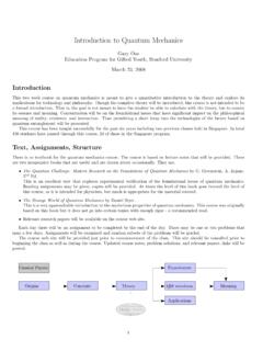
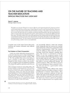
9 IEEEE lectron Dev. Lett., January 1998 Ultimate limit is air with K = 1 CuAirgapSource: Werner Pamler, Infinion 11EE311/ Low-k Dielectrics21 tanford UniversityaraswatAir-gap Experimental m (um)KeffExperimentalSimulatedKeff vs. Feature SizeTotal Capacitance (pF) OxideGapfillCumulative ProbabilitySignificant reduction in capacitance Ref: Shieh, et al., IEEE IITC, 1998EE311/ Low-k Dielectrics22 tanford Universityaraswat Air-Gap splits show significantly longer lifetimes than Gapfill split Leakage data indicates no breakdown well above operating Probabilitylog (Leakage Current) (A) Probability1103050709099 HDP appliedLeakageAir-gap ReliabilityRef: Shieh, et al., IEEE IITC, 200212EE311/ Low-k Dielectrics23 tanford Universityaraswat Rigid gapfill dielectric unable todeform and reduce stress duringelectromigration.
10 Flexible air-gap sidewall deforms Air-gaps lower the effectivemodulus of the dielectric. Lower modulus reduces stressduring electromigration. Effect of air-gap on modulus isgreater in high aspect ratio Gapfill DielectricAir-gap DielectricFIB Mill Cross-SectionReduced Stress in Air-gap StructuresRef: Shieh, et al., IEEE IITC, 2002