Transcription of M113 FAMILY OF VEHICLES (M113A2, M113A3, M106A2, …
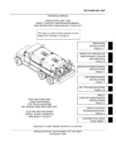
1 TM 55-2350-224-14 TECHNICAL MANUALTRANSPORT GUIDANCEM113 FAMILY OF VEHICLES (M113A2, M113A3, M106A2, M125A2, M548A1,M577A2, M667, M730A2, M741A1, M901A1, M981,M1015A1, M1059, M1064, AND M1068)APPROVED FOR PUBLIC RELEASE: DISTRIBUTION IS UNLIMITEDH E A D Q U A R T E R S , D E P A R T M E N T O F T H E A R M Y01 FEBRUARY 1993 TECHNICAL MANUALNo. TM 55-2350-224-14*TM 55-2350-224-14 HEADQUARTERSDEPARTMENT OF THE ARMYWASHINGTON, DC, 1 February 1993 TRANSPORT GUIDANCEM113 FAMILY of and scope ..Related Publications ..User Comments ..Definitions ..Warnings, Cautions, and Notes ..SAFETYG eneral ..EQUIPMENT DESCRIPTIONG eneral.
2 Technical Data ..Reduced Configuration ..HIGHWAY TRANSPORTGENERALG eneral ..Self-Delivery ..MOTOR VEHICLE TRANSPORTP rime Mover Selection ..Preparation ..Loading and Tiedown Procedures ..RAIL TRANSPORT GUIDANCEGENERALG eneral ..RAIL LOADINGR ailcar Selection..Preparation ..Loading Procedures ..MARINE TRANSPORTGENERALG eneral ..Safety ..SHIPLOADINGP reparation ..Loading Procedures ..Lifting Operations ..AIR TRANSPORTGENERALG eneral ..Safety ..Dangerous Materials ..TRANSPORT BY CARGO AIRCRAFTUSAF Cargo Aircraft ..US Army Aircraft ..Civil Reserve Air Fleet (CRAB) ..Preparation ..Conversion Tables ..1-11-21-31-41-51-61-71-81-92-12-22-32- 42-53-13-23-33-44-14-24-34-44-55-15-25-3 5-45-55-65-7.
3 References ..Methods of Identification for Inch-Size Chain ..Requirements for Converting the M981, M901, M901A1 (ITV) Launcher from Standard to TransportConfiguration and Back to Standard ..Detailed Procedures for securing the M577/A1/A2 Rear Ramp ..APPROVED FOR PUBLIC RELEASE: DISTRIBUTION IS UNLIMITED*This manual supersedes TM 55-2350-224-14, dated 1 April 55-2350-224-14 CHAPTER 1 INTRODUCTIONS ection I. GENERAL1-1. Purpose and ScopeThis manual is for transportation officers andother personnel responsible for safe transport ofthe M113 FAMILY of VEHICLES (FOV). It providestransportability guidance for safe shipping andreceiving of the M113 FOV.
4 It includes significanttechnical and physical characteristics of the vehi-cles as well as safety requirements for worldwidemovement by various modes of appropriate, this manual provides metricequivalents in parentheses next to US customaryunits of Related PublicationsAdditional information on transport procedurescan be found in the following:MTMCTEA Pamphlet 55-19, Tiedown Hand-book for Rail Pamphlet 55-20, Tiedown Hand-book for Highway Pamphlet 56 1, Surface Transporta-tion, Marine Terminal Lifting Pamphlet 70-1, Transportability forBetter Strategic 10-567/TO 13C7-16-171, Airdrop of Supplies and Equipment Rigging Tracked Person-nel Cargo 55-65, Strategic Deployment by 38-250/AFR 71-4, Preparation of HazardousMaterials for Military Air Reg 55-8, Loading and SecuringMilitary Wheeled and Tracked VEHICLES on Euro-pean 55-162, Permits for Oversize, Overweight.
5 OrOther Special Military Movements on PublicHighways in the United 55-228, Transportation by Water of Explo-sives and Hazardous User CommentsSend comments and recommendations for improv-ing this manual on a DA Form 2028 (Recom-Section GeneralTo ensure safe operation and movement, operatorsshould follow the precautions and safety consider-ations given below. Specific safety instructions aremended Changes to DA Publications and BlankForms) or a marked copy of a page or pages of themanual to Director, MTMC Transportation Engi-neering Agency, ATTN: MTTE-TR, 720 ThimbleShoals Blvd, Suite 130, Newport News, DefinitionsThe following definitions are used throughout thismanual:a.
6 Breaking Strength (BS). The stress at which apart (wire rope) actually CONUS. Continental United Curb Weight (CW). Total weight of operablecarrier, including fuel, all system fluids, and on-vehicle basic issue items (BII). CW does not in-clude crew FISTV. Fire Support Team Gross Vehicle Weight (GVW). CW plus maxi-mum Total Load Restraint (TLR). The TLR givenfor highway, rail,and marine modes includesallowances for shipping directions and typical tie-down angles. For example, the highway TLR is GVW: x 20,000 pounds = 30,000 TOW. Tube-Launched, Optically Tracked,Wire- guided Warnings, Cautions, and NotesThroughout this manual the following special mes-sages emphasize important or critical information:**WARNINGS**Instructions that must be followed to pre-vent serious injury to, or death of, person-nel.
7 **CAUTION**Instructions that must be followed to pre-vent damage to, or destruction of, equip-ment.*NOTE*An operating procedureceive special throughout thetions, and When the rampcarriers (except thethat should re-manual as warnings, cau-door latch on any of theM113A3, M548, M548A1,1-1TM 55-2350-224-14M667, M730A2, M901, M901A1, M981, M1015A1,and M1064) is not functioning properly, use theprocedure given in appendix Check each carrier to ensure all loose itemsare appropriately secured per instructions in therespective operator s All carriers must be driven only by When a carrier is being driven, the driver shatch cover must be secured in the fully open orfully closed If a track is thrown while the carrier is inoperation, do not apply brakes unless absolutelynecessary.
8 Instead, let the carrier coast to Do not mount or dismount a carrier when it isin The driver must bring the carrier to a com-plete stop before entering or leaving a Anytime carriers are operated in reverse, orwithin 20 feet of a building or other carrier, a ground guide must direct driver Do not operate the engine in an enclosed areawithout adequate High voltage in the M19 periscope can causeserious injury. Always connect the power cable tothe periscope before turning the master powerswitch and the infrared (IR) power switch to disconnect the power cable from the peri-scope until the image on the screen Ill.
9 EQUIPMENT DESCRIPTION1-7. Generala. The M113 FOV are fully tracked, self-propelled carriers, and are either thick skinned(armored) or thin skinned (unarmored). The ar-mored variants are derived from the M113A2 orM113A3, and the unarmored are derived from theM548. The M667 guided missile carrier is a specialexception. It is thin skinned, but is not based onthe All of the variants are powered by a dieselengine and are supported by a torsion-bar suspen-sion. Various product improvements on some vari-ants have resulted in transmission, suspension,armor, and power upgrades. The carriers vary inheight and weight, but unless otherwise noted,are considered the same for transportability The following paragraphs contain the specificadministrative and technical data that affecttransportability for each of the individual subsection contains a vehicle picture and therelating transportability characteristics and datanecessary for safe movement.
10 For transportabilitypurposes, the pictures of the newest versions (Al,A2, and A3) are representative of the older M106, M106A1, and M106A2 (figs1-1 and 1-2). This carrier is designed to trans-port the 107-mm ( ) M30 mortar and M30 is mounted on a turntable in the person-nel compartment and is fired to the rear with themortar hatch mortar may be dis-mounted and fired from the ground by using theM24A1 mortar mount thatThe M106 was convertedwas then converted to the1-2is stored on the the M106A1, whichM106A2. The M106A2is capable of Low Altitude Parachute ExtractionSystem (LAPES) M106, M106A1, and M106A2 (figs1-1 and 1-2).