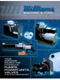
Transcription of MACHINE & TOOL BRAND Hydraulic Power Units
1 Williams MACHINE & Tool204 Plastic LaneMonticello, IA 52310-9472 USAP hone: (319) 465-3537 Pump Serial No. _____Fax: (319) 465-5279E-mail: Model No. _____Web Site: & TOOL2550 Rev. 1/10 NOTICE: This manual is to remain with truck after pump unit is 3-Piston PumpsDC 6-Piston PumpsDC Split-Flow Piston PumpsDC Gear PumpsInstructions for Williams Hydraulic Power UnitsHydraulic Power UnitsBRANDE nergy Manufacturing Company, 6/13 READ & UNDERSTAND THIS MANUAL BEFORE ATTEMPTING MAINTENANCE OR REPAIRTo the Owner/Operator:Read this manual thoroughly. The information presented in this manual will assist you to install, operate, and servicea Hydraulic Power unit. Keep this manual with the unit at all this manual you will see the following safety alert symbols:!CAUTION!WARNING!DANGER!This symbol indicates a personal safety alert, your safety is a potentially hazardous situation, which,if not avoided, may result in moderate a potentially hazardous situation, which,if not avoided, could result in death or serious an imminently hazardous situation, which,if not avoided, will result in death or serious of ContentsTo the 2 Safety InformationSafety 3 - 4 Safety Decal 5 Installation/Replacement 6 Operating 7 Charging a Hydraulic 8 Parts List 9 - 1812 General InformationThe purpose of this manual is to assist the owner/operator in maintainingand operating Williams MACHINE & Tool Hydraulic Power Units .
2 Read itcarefully before attempting operation, maintenance, or ChecklistBefore operating hoist, check the hoistmanufacturer s recommended maximumpayload. Do not overload the and understand all the safety decalsand signs on the truck hoist and Williams MACHINE & Tool Hydraulic Power sure that the hoist body prop andpump unit are in place and operationalbefore attempting to operate the Checklist Before UseBefore operating a loaded truck body,make sure the truck is on level, firm operating the truck hoist, check tomake sure the area is clear of all personneland the hoist controls from the cab duringdumping operations. Release tailgate controlsbefore lifting the purpose of this manual is to assist the owner/operator in maintaining and operating Williams Hydraulic Power it carefully before attempting operation, maintenance or AWAY! Serious injury or DEATH will result from truck box falling.
3 Truck box will fall in 1 second, crushing you if lever is moved. Body prop will not hold up a loaded box. Understand safety book before servicing or adjusting. Replace valve guard if missing or damaged. GUARD & SAFETY BOOK AVAILABLE FROM:Williams MACHINE & Tool204 Plastic Lane Monticello, IA 52310-9472 USAP hone: (319) 465-3537 Fax: (319) Site: !DANGER!Safety Decals1. Read and understand this manual and obey all safety decals before operating the Hydraulic Power Never go under a truck box, loaded or unloaded, unless the truck box has been properly Before operating a truck hoist, check to make sure the area is clear of all personnel and Never reach over the truck frame unless the truck box is properly Never drive the truck unless the truck box is completely p/n 1842 Williams p/n 1840 Williams p/n 1595 Williams Use automobileautomatic transmissionfluid (ATF) Make sure the fluid andall components are clean Fill reservoir to 3/4 ( cm) from the top Cycle system severaltimes to be sure all airis MACHINE & ToolMonticello, IA USA1842159518404 Safety DecalsDO NOT GO NEAR LEAKS!
4 High pressure oil easily punctures skin causing serious injury, gangrene or death. If injured, seek emergency medical help. Immediate surgery is required to remove oil. Do not use finger or skin to check for leaks. Lower load or relieve Hydraulic pressure before loosening !Williams p/n 1858 Williams p/n 1974 WARNING!DO NOT OPERATE PUMP UNIT UNTIL THE FOLLOWING STANDARDS ARE MET: USE 00 Power CABLE ON LENGTHS UP TO 10 FEET ( M) FROM BATTERY. USE 000 Power CABLE ON CABLE LENGTHS 11 TO 20 FEET ( TO M) FROM BATTERY. MOUNT PUMP UNIT TO THE VEHICLE WHERE A GROUND EQUAL TO OR LARGER THAN THE Power CABLE IS MAINTAINED BETWEEN THE PUMP MOUNTING SURFACE AND THE VEHICLE ENGINE BLOCK (CHECK GROUND CONTINUITY BEFORE OPERATING PUMP). (REFER TO INSTALLATION INSTRUCTIONS FOR FURTHER IMPORTANT INFORMATION)*FAILURE TO MEET THESE STANDARDS: MAY RESULT IN SEVERE INJURY OR DEATH. WILL VOID PUMP UNIT WARRANTY.
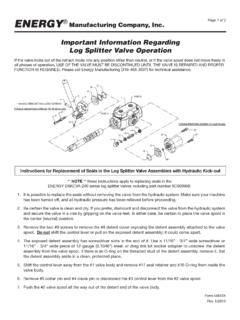
5 MAY CAUSE DAMAGE TO THE VEHICLE AND/OR VEHICLE ELECTRICAL MACHINE & TOOL IS NOT RESPONSIBLE FOR PERSONAL INJURY, DEATH ORVEHICLE AND/OR EQUIPMENT INSTALLATION INSTRUCTIONS AND/OR DECALS AVAILABLE FROM:WILLIAMS MACHINE & TOOL204 Plastic Lane Monticello, IA 52310-9472 USAP hone: (319) 465-3537 Fax: (319) Site: Decal Locations(See pages 3 & 4 for decal details and text)DC electric pump Units on square/round reservoirs(Solenoid operated control valves)6 Installation/Replacement Instructions1. Fabricate the necessary hardware and bracketry to install the Hydraulic Power unit to the truck that a ground is maintained between the Hydraulic Power unit and the vehicle that is equal toor larger than the main Power cable. (Reference Note below on grounding.)2. Install Hydraulic hoses from the control valve to the hoist cylinder. Use Hydraulic hoses with a pressurerating equal to or greater than the pressure at which the system will be operating.
6 Information sheetsfor determining lift and lower ports for the control valve have been included with the Install switch cord from the Hydraulic Power unit to the cab of the truck. Route the cord around allhazards which may damage the cord such as catalytic converters, exhaust manifolds, mufflers, sure the cord is not crushed, pinched or the outer casing is damaged. Use tie downs to properlysecure the To ensure proper wiring, valve schematics have been included with this book to show proper wiringdiagrams for the switch and control Install the mail Power cable to the starter solenoid on the motor of the Hydraulic Power : Do not attach the Power cable to the main Power source (battery) at this 00 Power cable on lengths up to 10 feet ( m) from the battery to the Power 000 Power cable on lengths from 11 to 20 feet ( to m) from the battery to the Power : A ground equal to or larger than the Power cable is required between the Hydraulic Power unit andthe vehicle.
7 (Check for continuity before operating unit.) If the Hydraulic Power unit is attached tothe vehicle frame, it may be required that a separate ground cable be mounted between the hydraulicpower unit and vehicle engine block. This requirement is necessary due to some vehicle frameshaving a protective coating which does not allow for an adequate Fill reservoir 3/4 ( cm) to 1 ( cm) from the top. Use a premium fluid for Hydraulic recommend automobile ATF (Automatic Transmission Fluid). These fluids provide good sealcompatibility, protection against wear, ample rust protection and excellent anti-foam Check unit for proper wiring and grounding. Ensure switch is wired per the included Attach the Power cable to the Power Check to make sure all persons and/or all equipment is clear of the area before operating the truck not attempt any repairs or adjustments to the truck hoist, truck box or Hydraulic Power unit until thetruck box is properly blocked/braced.
8 !DANGERB efore beginning installation work, make sure the truck box is empty andproperly blocked/braced. Always disconnect Hydraulic hoses from the valveto hoist cylinder after the truck box is properly blocked/braced. Seriousinjury or death will result from truck box falling in one second or less.!CAUTIONF ailure to maintain an adequate ground between thehydraulic Power unit and the truck frame may resultin damage to the Hydraulic unit and/or the vehicleelectrical InstructionsTo Raise a Load:1. Release the tailgate controls before raising the truck From inside the cab, push the switch towards the up/raise position. When the truck box is at theappropriate height, release the Dump a loaded box slowly. Be careful the load does not shift Do not drive the truck while the truck box is Lower a Load:1. From inside the cab, push the switch towards the down/lower position. When the box is at theappropriate height, release the Do not drive the truck while the truck box is raised.
9 !DANGERN ever go under a raised truck box, unless the truck box is properlyblocked/braced. Serious injury or death will result from truck boxfalling in one second or a Hydraulic SystemSingle Acting Cylinder Applications:The reservoir must be sized to handle the full displacement of the lifting end of the cylinder. Fill the reservoir3/4 to 1 ( to cm) from the top when the cylinder is completely Acting Cylinder Applications: Without Recycle CapabilitiesThe reservoir must be sized to handle the full displacement of the lifting end of the cylinder. Fill the reservoir3/4 to 1 ( to cm) from the top when the cylinder is completely Acting Cylinder Applications: With Recycle CapabilitiesThe reservoir can be sized to handle the total displacement of the cylinder rod only. To charge a reservoir ona recycle application, follow the steps below:1. Fill the reservoir 1 ( cm) from the top when the cylinder is completely Operate the pump for a short time to extend the cylinder.
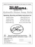
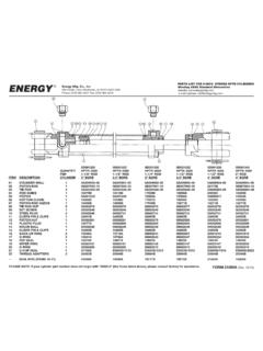
10 Do not run the reservoir dry as this willintroduce air into the Properly block/brace the truck box. Never go under the truck box unless it is properly Again, fill the reservoir 1 ( cm) from the top. Repeat steps 2,3, and 4 until the cylinder iscompletely Retract the cylinder completely and adjust the fluid level inside the reservoir 3/4 to 1 ( to cm)from the : Never fill the reservoir completely when the cylinder is even slightly extended. The reservoir willoverflow with fluid when it is retracted.!CAUTIONUsed Hydraulic fluid is considered hazardous waste insome states. If used fluid is spilled, check your localregulations for proper handling & cleaning Piston Pump and Manifold Assembly10 ItemPart Req dPart Description118573 Cap Screw, 5/16 - 18 x 4-1/2 , GR5210303 Washer, 21/64 ID Stud w/Pin410096 Washer, 1/16 Thk 1/2 ID , Long Exhaust Port Stud610156 Bearing, 5/16 Chrome Ball716366 Seat, Electric Pump815794 Plug, 1/16 NPT w/Sealant920041 Casting Machined, 6 Piston (Not Sold Separately)1016421 Spring, Return Plate Pivot1116351 Pivot, Piston Return Plate1216336 Piston (Not Sold Separately)