Fluid power graphic symbols
Found 24 free book(s)
Chapter 4 Fluid Power Standards and Symbols - PBworks
etshare.pbworks.comChapter 4 Fluid Power Standards and Symbols Language of the Industry. ... Fluid power graphic symbols consist of basic figures: – Lines – Circles – Squares ... Fluid Power Symbols and Circuit Diagrams Circuit diagram schematics must: –Include all components and connections

ENGINEERING YOUR SUCCESS. - parker.com
www.parker.comFluid Power Graphic Symbols Actuator Technical Information Vacuum Technical Information Valve Technival Information H Technical Data Pneumatic Products Fluid Power Graphic Symbols Air Line Pressure Regulator adjustable, relieving Lubricator with automatic filling Lubricator with manual drain Lubricator
SymbolDescription Description Symbol Description
www.parker.comFluid Power Graphic Symbols H Technical Data Pneumatic Products Fluid Power Graphic Symbols Air Line Pressure Regulator adjustable, relieving Lubricator with automatic filling Lubricator with manual drain Lubricator less drain Automatic Drain Oil Removal Filter Filter / Separator with automatic drain
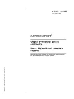
AS 1101.1-1993 Graphic Symbols for general engineering ...
www.saiglobal.comGraphic Symbols for general engineering Part 1: Hydraulic and pneumatic systems [ISO title: Fluid power systems and components–Graphic symbols and circuit diagrams, Part 1: Graphic symbols] This is a free 7 page sample. Access the full version online. This Australian Standard was prepared by Committee ME/35, Fluid Power Systems and Components ...

National Fire Protection Association Report
www.nfpa.orgISO 1219-1, Fluid power systems and components — Graphic symbols and circuit diagrams — Part 1: Graphic symbols for Conventional Use and Data-Processing Applications, 20062012. ISO 1219-2, Fluid power systems and components — Graphic symbols and circuit diagrams — Part 2: Circuit diagrams, 19952012.

National Fire Protection Association Report - nfpa.org
www.nfpa.orgISO 1219-1, Fluid power systems and components — Graphic symbols and circuit diagrams — Part 1: Graphic symbols , 2006 for Conventional Use and Data-Processing Applications, 2012. ISO 1219-2, Fluid power systems and components — Graphic symbols and circuit diagrams — Part 2: Circuit diagrams, 1995 2012.
MILITARY STANDARD <.< ENGINEERING DRAWING PRACTICES
www.product-lifecycle-management.comMILITARY STANDARD ENGINEERING DRAWING PRACTICES ANsc ti/A f) ISTRIBUTION STATEM~ . ... Graphic Symbols for Plumbing Fixtures for Diagrams. Used in Architecture and Building Construction Graphic Symbols for Electric and Layout Drawings Used in Architecture and Building Construction Graphic Symbols for Fluid Power Diagrams.Symbols for Welding and ...

GCC STANDARDIZATION ORGANIZATION (GSO) - NIST
tsapps.nist.govGCC Standardization Organization (GSO) is a regional Organization which ... ISO 1219-1:1991, Fluid power systems and components — Graphic symbols and circuit diagrams — Part 1: Graphic symbols ISO 2942:1994, Hydraulic fluid power — Filter elements — Verification of fabrication integrity and
AS 1101.1-2007 Graphic symbols for geneal engineering-Part ...
www.saiglobal.comand maintenance of fluid power systems with a system of graphic symbols for use on components and circuit diagrams and for data-processing applications. This Standard is identical with and has been reproduced from ISO 1219-1:2006, Fluid power

ISO 1219 1:2006 Symbol Library - Virtual Interconnect Shop
www.virtual-interconnect-shop.comISO 1219-1:2006 Symbol Library ... includes graphic symbols for circuit diagrams of fluid power systems and components. Simply download the library and get ... International Organization for Standardization’s graphic symbols for fluid power systems and components 513 127 3 3 4
Practical Hydraulics Course - Fluid Power Education ...
fpti.org2 - Hydraulic Symbols 1) Correctly describe the meanings of: a) a complete graphic symbol b) a simplified graphic symbol c) pictorial symbol. d) cutaway symbol

HYDRAULIC CIRCUIT DESIGN AND ANALYSIS
www.arsinmachine.comIt is very important for the fluid power ( Hydraulics and Pneumatics ) designer to have a working knowledge of components and how they operate in a circuit. Hydraulic circuits are developed through the use of graphical symbols for all

Binary Logic Diagrams for Process Operations
www.wccandm.servicesISA-S5.2 — Binary Logic Diagrams for Process Operations ISBN 0-87664-331-4. ANSI/ISA-S5.2-1976 (R 1992) 3 ... Standard Y32.14.1973, Graphic Symbols for Logic Diagrams, which the committee attempted to follow so far as practical for the intended users of ... Reference was also made to National Fluid Power Association
Fluid Power Graphic Symbols - parkerhannifin.be
www.parkerhannifin.beFluid Power Graphic Symbols AIR LINE PRESSURE REGULATOR adjustable, relieving LUBRICATOR with automatic filling LUBRICATOR with manual drain LUBRICATOR less drain AUTOMATIC DRAIN OIL REMOVAL FILTER FILTER/SEPARATOR with automatic drain FILTER/SEPARATOR with manual drain AIR LINE PRESSURE REGULATOR pilot controlled,

A GRAPHICAL SYMBOLS FOR PIPING SYSTEMS AND PLANT
booksite.elsevier.comAPPENDIX A GRAPHICAL SYMBOLS FOR PIPING SYSTEMS AND PLANT A- 3. Upshot heater Where complex burners are employed the ‘‘burner block’’ may be detailed elsewhere on the drawing, thus ... Fluid contacting vessel (basic symbol) Fluid contacting vessel Support grids and distribution details may be shown Reaction or absorption vessel
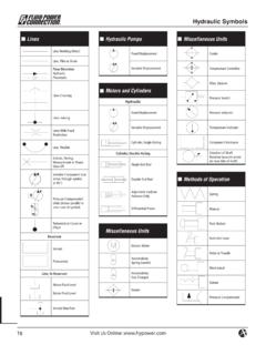
Hydraulic Symbols - HyPOWER
www.hypower.comHydraulic Symbols Lines Line, Working (Main) Line, Pilot or Drain Flow Direction Hydraulic Pneumatic Lines Crossing Lines Joining Lines With Fixed Restriction ... Color Code for Fluid Power Schematic Drawings Black Intensifi ed Pressure Red Supply Intermittent Red Charging Pressure Intermittent Red Reduced Pressure
ENGINEERING SYMBOLOGY, PRINTS, AND DRAWINGS Module 2 ...
sites.ntc.doe.govModule 2: Engineering Fluid Diagrams and Prints iv REFERENCES ASME Y14.5-2009, Dimensioning and Tolerancing. IEEE Std 315-1975 (Reaffirmed 1993), Graphic Symbols for Electrical and

NOT MEASUREMENT SENSITIVE MIL-DTL-81310G(AS) 31 March 2008 ...
everyspec.comASME-Y32.2.6 - Graphic Symbols for Heat-Power Apparatus (Copies of the documents listed above are available online www.asme.org or from ASME Information Central Orders/Inquiries, P.O. Box 2300, Fairfield, NJ 07007-2300.)

Hydraulic Symbols
hydraulicsonline.co.uksymbols for hydraulic circuits fluid treatment breather with filter filter (e.g. 2fa...) filter with indicator (e.g. ifrf...+ ifri-d) water / oil cooler air / oil cooler heater ... fluid level check valve shut-off valve single acting telescopic cylinder double acting double rod cylinder closed centre a
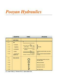
Fluid power graphics - BTP Hydraulics
iranfluidpower.comPooyan Hydraulics 2) L= Length of dash, E = Thickness of line, D = Space between lines DESCRIPTION SYMBOL APPLICATION 1.1 1.1.1 1.1.1.1 1.1.1.2 1.1.1.3

American National Standard - National Optical Astronomy ...
www.noao.eduThis American National Standard is a revision and expansion of American National Standard Graphic Symbols for Electrical and Electronics Diagrams, Y32.2-1970 (IEEE Std 315-1971). A variety of specialized symbols originally used for aircraft applications have been added to make
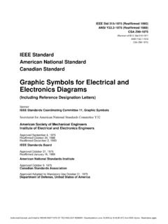
Graphic Symbols for Electrical and Electronics Diagrams
www.ee.iitb.ac.inSymbols for Electrical and Electronics Diagrams of the American National Standards Committee Y32, Graphic Symbols and Designations. There has been close cooperation between the industry and DOD representatives to
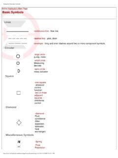
Airline Hydraulic's Main Page Basic Symbols
www.me.ua.eduHydraulic Schematic Symbols Airline Hydraulic's Main Page Basic Symbols Lines-continuous line - flow line -dashed line - pilot, drain -envelope - long and short dashes around two or more component symbols.
xxx xxx App 879605 - CAE Users
homepages.cae.wisc.eduAppendix B Table B. Pipe Symbols (continued) Air Conditioning BR B C H C H R C C R D H R D R L R S Heating Air-Relief Line Boiler Blow-Off Compressed Air Condensate or Vacuum Pump Discharge
Similar queries
Chapter 4 Fluid Power Standards and Symbols, Fluid Power Graphic Symbols, Fluid Power Symbols, Graphic Symbols for general engineering, Fluid Power, Graphic Symbols, National Fire Protection Association, MILITARY STANDARD <.< ENGINEERING DRAWING PRACTICES, MILITARY STANDARD ENGINEERING DRAWING PRACTICES, Symbols, GCC Standardization Organization GSO, 2007 Graphic symbols for geneal, 1219 1:2006 Symbol Library, 1219-1:2006 Symbol Library, Practical Hydraulics Course, Graphic, HYDRAULIC CIRCUIT DESIGN AND ANALYSIS, Binary Logic Diagrams for Process Operations, GRAPHICAL SYMBOLS FOR PIPING SYSTEMS, Fluid, Hydraulic Symbols, ENGINEERING SYMBOLOGY, PRINTS, AND, Power, Fluid power graphics, American National Standard, American National Standard Graphic Symbols, Airline Hydraulic's Main Page Basic Symbols, Symbols Airline Hydraulic's Main Page Basic Symbols, Xxx xxx App 879605