Transcription of xxx xxx App 879605 - CAE Users
1 Page 2 2/26/08 3:46:53 PM aptara1 /Volumes/ju108/MHGL125/MHGL125_indd%0/BM . Appendix A. Abbreviations and symbols Across Flats .. ACR FLT Kilogram ..kg American National Standards Kilometer .. km Institute .. ANSI Left Hand .. LH. Approximate .. APPROX Liter ..L. Assembly .. ASSY Material .. MATL. Bill of Materials .. B/M Maximum .. MAX. Bolt Circle .. BC Maximum Material Condition .. M or MMC. Carbon Steel .. CS Meter .. m Casting .. CSTG Metric Thread .. M. Cast Iron .. CI Micrometer .. m Center Line .. or CL Millimeter ..mm Center to Center .. C to C Minimum .. MIN. Centimeter .. cm Nominal .. NOM. Chamfer .. CHAM Number .. NO. Cold-Rolled Steel .. CRS Outside Diameter .. OD. Concentric .. CONC Radius .. R. Counterbore .. or CBORE Reference or Reference Dimension .. ( ) or REF. Counterdrill .. CDRILL Right Hand .. RH. Countersink .. or CSK Slotted .. SLOT. Depth .. DP or Spherical ..SPHER. Diameter .. or DIA Spotface .. or SFACE.
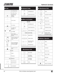
2 Drawing .. DWG Square .. or SQ. Equally Spaced .. EQL SP Steel .. STL. Finish All Over .. FAO Symmetrical.. or SYM. Gage .. GA Taper Flat .. Heat Treat .. HT TR Taper Round .. Hexagon .. HEX Through .. THRU. Inside Diameter .. ID Tolerance .. TOL. International Standards Organization ..ISO Gage .. USG. 2 Appendix A. Page 4 2/26/08 3:46:55 PM aptara1 /Volumes/ju108/MHGL125/MHGL125_indd%0/BM . Appendix B. Pipe symbols Table B. Pipe symbols Bell &. Flanged Screwed Welded Soldered Spigot M. Motor- M M. Operated Globe Valve Motor- M M M. Operated Globe Hose Valve . Angle Hose Valve . Gate Hose Valve . Globe Lockshield Valve Quick-Opening Valve Safety Valve Governor- Operated Reducing Check Valve (Straight Way). Cock Diaphragm Valve Float Valve Gate Valve 4 Appendix B. Page 5 2/26/08 3:46:56 PM aptara1 /Volumes/ju108/MHGL125/MHGL125_indd%0/BM . Appendix B. Table B. Pipe symbols (continued). Bell &. Flanged Screwed Welded Soldered Spigot Bull Plug Pipe Plug Concentric Reducer Eccentric Reducer Sleeve Tee (Straight Size).
3 Tee (Outlet Up). Tee (Outlet Down). Tee (Double Sweep). 2 2 2 2 2. Reducing Tee 6 4 6 4 6 4 6 4 6 4. Tee (Single Sweep). Side Outlet (Outlet Down). Side Outlet (Outlet Up). Union Angle Valve . Check Angle Valve . Gate (Elevation). Angle Valve . Gate (Plan). Angle Valve . Globe (Elevation). Angle Valve . Globe (Plan). Automatic Valve . By-Pass Appendix B 5. Page 6 2/26/08 3:46:59 PM aptara1 /Volumes/ju108/MHGL125/MHGL125_indd%0/BM . Appendix B. Table B. Pipe symbols (continued). Bell &. Flanged Screwed Welded Soldered Spigot Long Radius LR LR. 2 2 2. Reducing 4 4 4. Side Outlet (Outlet Down). Side Outlet (Outlet Up). Street Connecting Pipe Joint Expansion Joint Lateral Orifice Flange Reducing Flange 6. 4. Bushing Cap 2 2 2 2 2. 6 6 6 6. Reducing 6 6 6 6 6 6. Cross 4 4 4 4 4. Straight Size Cross Crossover 45 Elbow 90 Elbow Elbow (Turned Down). Elbow (Turned Up). Base Double Branch 6 Appendix B. Page 7 2/26/08 3:47:00 PM aptara1 /Volumes/ju108/MHGL125/MHGL125_indd%0/BM .
4 Appendix B. Table B. Pipe symbols (continued). Air Conditioning Brine Return BR. Brine Supply B. Circulating Chilled or Hot-Water Flow CH. Circulating Chilled or Hot-Water Return CHR. Condenser Water Flow C. Condenser Water Return CR. Drain D. Humidification Line H. Make-Up Water Refrigerant Discharge RD. Refrigerant Liquid RL. Refrigerant Suction RS. Heating Air-Relief Line Boiler Blow-Off Compressed Air A. Condensate or Vacuum Pump Discharge O O O. Feedwater Pump Discharge OO OO OO. Fuel-Oil Flow FOF. Fuel-Oil Return FOR. Fuel-Oil Tank Vent FOV. High-Pressure Return High-Pressure Steam Hot-Water Heating Return Hot-Water Heating Supply Appendix B 7. Page 8 2/26/08 3:47:02 PM aptara1 /Volumes/ju108/MHGL125/MHGL125_indd%0/BM . Appendix C. Reference Tables In the United States, the governing body International drafting standards are con- responsible for the standards established for tech- trolled by the International Standards nical and engineering drawing is the American Organization (ISO).
5 However, since the National Standards Institute (ANSI). How- United States holds a leadership role in ISO, ever, ANSI has enlisted the help of the American the international standards continue to move Society of Mechanical Engineers (ASME) toward those established and maintained by to assist in the revision, maintenance, and mar- ASME. The differences become less noticeable keting of these standards. A catalog of their draft- with each revision. ing standards and other ASME publications is Selected standards useful to the drafter are available by writing to ASME, 22 Law Drive, Box listed below. Since all standards are constantly 2900, Fair eld, NJ 07007-2900. Standards estab- under revision, it is important to consult lished for other technical elds, also controlled the most current ASME catalog for the latest by ANSI, are maintained by their respective pro- editions. fessional organizations. ANSI/ASME Standards Standards for Drawings Abbreviations for Use on Drawings and Text.
6 Decimal Inch Drawing Sheet Size and Format .. Metric Drawing Sheet Size and Format .. Line Conventions and Lettering .. Multi- and Sectional-View Drawings .. Pictorial Drawing .. Dimensioning and Tolerancing .. Preferred Limits and Fits for Cylindrical Parts .. Preferred Metric Limits and Fits .. General Tolerances for Metric Dimensioned Products .. Screw Thread Representation .. Screw Thread Representation (Metric Supplement) .. Gear Drawing Standards Part 1: For Spur, Helical, Double Helical, and Rack .. Gear Drawing Standards Part 2: Bevel and Hypoid Gears .. Castings and Forgings .. Mechanical Spring Representation .. Types and Applications of Engineering Drawings.. Surface Texture symbols .. Surface Texture (Surface Roughness, Waviness, and Lay .. Engineering Drawing Practices .. Graphic symbols for Pipe Fittings, Valves, and Piping .. Graphic symbols for Heating, Ventilating, and Air Conditioning .. Graphic symbols for Plumbing Fixtures for Diagrams Used in Architecture and Building Construction.)
7 8 Appendix C. Page 9 2/26/08 3:47:04 PM aptara1 /Volumes/ju108/MHGL125/MHGL125_indd%0/BM . Appendix C. Preferred Metric Sizes for Fluid Power Diagrams .. Preferred Metric Sizes for Round, Square, Rectangular, and Hexagon Metal Products .. Preferred Metric Sizes for Tubular Metal Products Other Than Pipe .. Preferred Metric Equivalents of Inch Sizes for Tubular Metal Products Other Than Pipe.. Welded and Seamless Wrought Steel Pipe .. Fasteners in Metric Units Metric Small Solid Rivets .. Metric Hex Cap Screws .. Metric Formed Hex Screws .. Metric Heavy Hex Screws .. Metric Hex Bolts .. Metric Heavy Hex Bolts .. Square Head Bolts (Metric Series) .. Metric Hex Nuts, Style 1 .. Metric Hex Nuts, Style 2 .. Metric Slotted Hex Nuts .. Metric Heavy Hex Nuts .. Socket Head Cap Screws .. Hexagon Socket Flat Countersunk Head Cap Screws.. Metric Series Socket Set Screws .. Cotter Pins (Metric Series) .. Square and Rectangular Keys and Keyways.
8 Woodruff Keys and Keyways .. Fasteners in Customary Units Small Solid Rivets .. Large Rivets .. Square and Hex Bolts and Screws (Inch Series) .. Square and Hex Nuts (Inch Series) .. Clearance Holes for Bolts, Screws, and Studs.. Socket Cap, Shoulder, and Set Screws, Hex and Spline Keys (Inch Series) .. Round Head Bolts (Inch Series) .. Wood Screws (Inch Series) .. Slotted Head Cap Screws, Square Head Set Screws, and Slotted Headless Set Screws .. Machine Screws and Machine Screw Nuts .. Taper Pins, Dowel Pins, Straight Pins, Grooved Pins, and Spring Pins (Inch Series) .. Lock Washers (Inch Series) .. Plain Washers .. Keys and Keyseats .. Woodruff Keys and Keyseats .. ANSI/AWS Standard symbols for Welding and Nondestructive Testing .. AWS Appendix C 9. Page 10 2/26/08 3:47:06 PM aptara1 /Volumes/ju108/MHGL125/MHGL125_indd%0/BM . Appendix C. The Reference Tables The tables that follow are needed to work some of the problems in this edition of Mechanical Drawing: Board and CAD Techniques.
9 These tables have been adapted from the ANSI/ASME standards for use in this book. Although most of the tables are self-explana- tory, the following sections provide additional information about some of them. American National Standard Limits and Fits Tables C-9 through C-16 are designed for use with the basic hole system of limits and ts described in Chapter 7, Dimensioning. Information from these tables is adapted from ASME , Preferred Limits and Fits for Cylindrical Parts. For larger sizes and additional information, refer to the standard. There are ve distinct classes of ts: RC Running or sliding clearance fits LC Locational clearance fits LT Transition clearance or interference fits LN Locational interference fits FN Force or shrink fits These ve classes of ts are placed in three general categories, as follows. Running and Sliding Fits (Table C-9). These ts provide a similar running performance, with suitable lubrication allowance, throughout the range of sizes.
10 The clearances for the rst two classes, used chie y as slid- ing ts, increase more slowly than for the other classes, so that accurate location is main- tained even at the expense of free relative motion. RC 1: Close sliding fits accurately locate parts that must assemble without perceptible play. RC 2: Sliding fits are for accurate location, but with greater maximum clearance than RC 1. Parts move and turn easily but do not run freely, and in the larger sizes may seize with small temperature changes. RC 3: Precision running fits are the closest fits expected to run freely. They are for precision work at slow speeds and light journal pressures. They are not suitable under appreciable temperature differences. RC 4: Close running fits are chiefly for running fits on accurate machinery with mod- erate surface speeds and journal pressures, where accurate location and minimum play are desired. RC 5 and RC 6: Medium running fits are for higher running speeds, heavy journal pressures, or both.