Transcription of HYDRAULIC CIRCUIT DESIGN AND ANALYSIS
1 HYDRAULIC CIRCUIT DESIGN AND ANALYSIS A HYDRAULIC CIRCUIT is a group of components such as pumps, actuators, and control valves so arranged that they will perform a useful task. When analyzing or designing a HYDRAULIC CIRCUIT , the following three important considerations must be taken into of of desired of operation It is very important for the fluid power ( Hydraulics and Pneumatics ) designer to have a working knowledge of components and how they operate in a CIRCUIT . HYDRAULIC circuits are developed through the use of graphical symbols for all components. The symbols have to conform to the ANSI of a Single - Acting HYDRAULIC Cylinder : A single-acting cylinder can exert a force in only the extending direction as fluid from the pump enters the blank end of the cylinder ( usually left side of the piston). Single- acting cylinder do not retract hydraulically. Retraction is accomplished by using gravity or by the inclusion of a compression spring in the rod end.
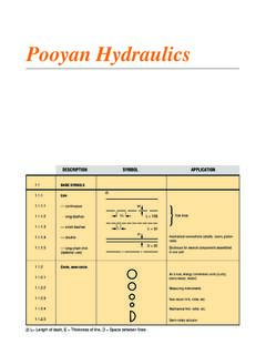
2 A Fig Symbol Force during extension stroke is , Fext = p * AP Velocity during extension stroke is , vP ext = QP / AP The force and velocity during retraction stroke depends upon spring rate as single acting cylinder do not retract hydraulically Figure shows a two- postion, three way, manually operated, spring offset directional control valve ( DCV ) used to control the operation of a single acting cylinder. In the spring offset mode, full pump flow goes the tank via the pressure relief valve. The spring in the rod end of the cylinder retracts the piston as oil from the blank end A drains back to the rank. When the valve is manually actuated the pump flow goes to the cylinder blank end A via DCV 1 position. This extends the cylinder. At full extension, pump flow goes through the relief valve. Deactivation of the DCV allows the cylinder to retract as the DCV shift into its spring offset mode.
3 C A D P T P R T F T Fig Control of Single -Acting HYDRAULIC Cylinder. C = Single acting cylinder P = Pump E = Electric Motor T = Tank F = Filter R = Relief Valve D =2-position, 3 way DCV Manually operated and spring Control of Double -Acting HYDRAULIC Cylinder : Double Acting cylinders can be extended and retracted hydraulically.
4 Thus, an output force can be applied in two directions. A B Fig Double acting cylinder1 0E The output force ( F ) and piston velocity of double acting cylinder are not the same for extension and retraction strokes. During the extension stroke, fluid enters the blank end ( A ) of the cylinder through the entire circular area of the piston ( AP ). However during the retraction stroke, fluid enters the rod end through the smaller annular area between the rod and cylinder bore ( AP AR ), where AP = piston area , and AR = rod area. Since AP = is grreater than ( AP AR ), the retraction velocity is greater than the extension velocity since the pump flow rate is constant. Similarly during the extension stroke, fluid pressure bears on the entire area of the piston( AP ). However during the retraction stroke, fluid pressure bears on the smaller annular area ( AP AR ).
5 The difference in area accounts for the difference in output force, with the output force is greater during extension. Extending stroke : Force, Fext = p * AP -------- 1 Velocity, vext = Qp / AP -----2 Retraction Stroke : Force, Fret = p * ( AP Ar ) --- 3 Velocity, vret = Qp / (AP Ar ) --- 4 It can be seen from the above 4 equations that force during extension stroke and velocity of piston during retraction stroke is greater for the same operating pressure and flow rate. The power developed by a HYDRAULIC cylinder for either the extension or retraction stroke, can be found out by (velocity multiplied by force) or from ( flow rate multiplied by operating pressure ) power ( kW ) = vp ( m / s ) * F ( kN ) = Q ( m3 / s) * p ( kPa ) Figure shows a CIRCUIT used to control a double acting HYDRAULIC cylinder.
6 When the four way valve is in centered configuration , the cylinder is hydraulically locked as the ports A and B is blocked. The pump flow is unloaded back to the tank at essentially atmospheric pressure. When the four way valve is actuated into the 1st position , the cylinder is extended against its load force Fload as oil flows to the blank end of the cylinder from port P through port A . Also, oil in the rod end of the cylinder is free to flow back to the tank via the four way valve from port B through port T. Note that the cylinder would not extend if this oil were not allowed to leave the rod end of the cylinder. When the four way valve is actuated into the 2st position , the cylinder is retracts against as oil flows to the rod end of the cylinder from port P through port B. Oil in the blank end of the cylinder is returned to the tank from port A to port T. At the end of the stroke, there is no system demand for oil. Thus, the pump flow goes through the relief valve at its pressure- level setting unless the four- way valve is deactivated.
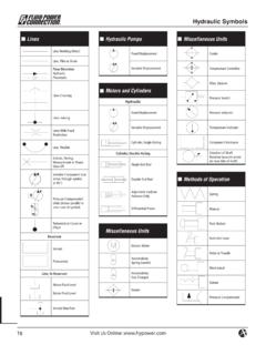
7 In any event the system is protected from any cylinder overloads. F LOAD C A B D P T E P R T F TFig Control of Double -acting HYDRAULIC cylinder. C = Double acting cylinder P = Pump E = Electric Motor T = Tank F = Filter R = Relief Valve D =3-position, 4 way ,Tandem center, Manually operated and Spring Centered DCV Problem 1.
8 A double acting cylinder is hooked up to reciprocate. The relief valve setting is 70 bars. The piston area is m2 and the rod area is m2. If the pump flow is / s, find the cylinder speed and load- carrying capacity for the : Relief valve pressure setting, p = 70 bars = 70 * 105 N /m2 Piston area, Ap = m2 Rod area, Ar = m2 1 0 2 Pump flow, Qp = m3/sa)Extending Stroke : Cylinder speed, vp ext = Qp / AP = / = m / s Load carrying capacity, Fload = p * AP = 70 * 105 * = 112000 N = 112kN b)Retracting Stroke : Cylinder Speed, vp Ret = Qp / (AP Ar) = / ( - ) = m / s Load carrying capacity, Fload = p * ( AP Ar ) = 70 * 105 * ( - = 80500 N = Regenerative CIRCUIT : Operation Figure shows a regenerative CIRCUIT that is used to speed up the extending speed of a double-acting HYDRAULIC cylinder.
9 Here the pipelines to both ends of the HYDRAULIC cylinder are connected to pump, one end (A) through the 2 / 3 way DCV and the other end (B) directly. The operation of the cylinder during the retraction stroke is the same as that of a regular double-acting cylinder. fluid flows through the DCV zero position from the actuator A side during retraction. In this position, fluid from the pump directly enters the rod end of the cylinder ( direct connection). fluid in the blank end drains back to the tank through the DCV as the cylinder the DCV is shifted to 1 position due to manual actuation, the cylinder extends. The speed of extension is greater than that for a regular double-acting cylinder because flow from the rod end (QR) regenerates with the pump flow (QP) to provide a total flow rate (QT), which is greater than the pump flow rate to the A side of the cylinder. ( Area of blank end is more than rod end, thereby blank end provide least resistance ) C A B D P T E P F T Fig Regenerative CIRCUIT .
10 C = Double acting cylinder P = Pump E = Electric Motor T = Tank F = Filter R = Relief Valve D =2-position, 3 way , Manually operated and Spring return DCVC ylinder Extending Speed The total flow rate entering the blank end (A) of the cylinder equals the pump flow rate plus the regenerative flow rate coming from the rod end of the cylinder:QT = QP + QR Or QP = QT - QR ---(1)We know that the total flow rate equals the piston area multiplied by the extending speed of the piston (Vpext). Similarly, the regenerative flow rate equals the difference of the piston and rod areas (Ap - Ar) multiplied by the extending speed of the piston.