Transcription of Managed Switch Hardware Installation Guide - Netgear
1 Managed Switch Hardware Ins tallat i o n G ui d e Models: M4100 Series August 2016. 202-11217-04. 350 East Plumeria Drive San Jose, CA 95134. USA. Netgear Managed Switch Support Thank you for purchasing this Netgear product. You can visit to register your product, get help, access the latest downloads and user manuals, and join our community. We recommend that you use only official Netgear . support resources. Contact your Internet service provider for technical support. Conformity For the current EU Declaration of Conformity, visit Compliance For regulatory compliance information, visit See the regulatory compliance document before connecting the power supply. Trademarks Netgear , Inc., Netgear and the Netgear Logo are trademarks of Netgear , Inc. Any non- Netgear trademarks are used for reference purposes only. Revision History Publication Part Number Publish Date Comments 202-11217-04 August 2016 Updated model numbers on page 13; minor editorial revisions.
2 202-11217-03 July 2016 Updated models in rack and wall Installation instructions. 202-11217-02 November 2013 202-11217-01 January 2013 2. Contents Chapter 1 Introduction Front Panels and LEDs.. 4. Rear Panels .. 9. Safety Instructions .. 10. Chapter 2 Hardware Installation Package Contents .. 13. Protecting against Electrostatic Discharge .. 13. Unpack the Hardware .. 14. Installation .. 14. Select a Location.. 15. Install the Switch .. 16. Install the M4100-D12G or M4100-D10-PoE Using Magnets .. 19. Check the Installation .. 20. Connect to Power and Check the LEDs .. 20. SFP Modules.. 21. Connect Equipment to the Switch .. 22. RJ-45 Ports .. 22. Connect a Console to the Switch .. 22. Chapter 3 Troubleshooting Troubleshooting Chart .. 24. Additional Troubleshooting Suggestions .. 25. Appendix A Technical Specifications Appendix B Default Configuration Settings 3. 1. Introduction 1. The Netgear ProSAFE M4100 Series Managed switches provide state-of-the-art, high-performance, IEEE-compliant network solutions.
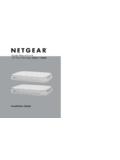
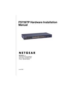
3 They include powerful management features that you can use to eliminate bottlenecks, boost performance, and increase productivity. The M4100 Series switches include the following: M4100-26G. M4100-50G. M4100-26-POE. M4100-26G-POE. M4100-50G-POE+. M4100-50-POE. M4100-D10-POE. M4100-D12G. M4100-12GF. M4100-D12G-POE+. M4100-24G-POE+. M4100-12G-POE+. This Guide describes Hardware Installation and basic troubleshooting for these Managed switches. These switches can be freestanding, wall mounted, or rack mounted in a wiring closet or an equipment room. For information about features for each product, visit the Netgear website at Front Panels and LEDs The following figures show the front panels of the ProSAFE 4100 series Managed switches. The front panel contains LEDs, a Reset button, a USB flash port, RJ45 ports, copper (RJ-45)/fiber (SFP) combo ports, and USB console selection slide Switch , and USB console port.
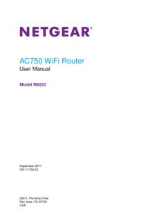
4 4. Netgear Managed Switch LEDs USB port Reset button RJ-45 ports SFP ports Figure 1. M4100-26G front panel Power Fan RPS. Combo Ports RJ45 SPD/Link/ACT mode: Green = 1G Yellow = 10/100M Blink = ACT. Reset USB SFP SPD/Link/ACT mode: Green = Link at 1G Yellow = Link at 100M Blink = ACT. LEDs USB port Reset button RJ-45 ports SFP ports Figure 2. M4100-50G front panel LEDs USB port Reset button POE ports RJ-45 ports SFP ports Figure 3. M4100-26-POE front panel LEDs USB port Reset button POE ports RJ-45 ports SFP ports Figure 4. M4100-50-POE front panel Introduction 5. Netgear Managed Switch LEDs USB port Reset button POE ports RJ-45 ports SFP ports Figure 5. M4100-26G-POE front panel LEDs USB port Reset button POE ports RJ45 ports SFP ports Figure 6. M4100-50G-POE+ front panel LEDs USB port Reset button POE ports RJ45 ports SFP ports Figure 7. M4100-D10-POE Front Panel LEDs USB port Reset button RJ45 ports SFP ports Figure 8.
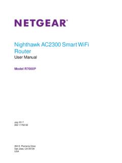
5 M4100-D12G front panel Introduction 6. Netgear Managed Switch M4100-24G-POE+. PoE SPD/Link/ACT. PoE (Max 30W per port): Off = No PD SFP SPD/Link/ACT mode Power Green = PoE Powered Green = Link at 1G. Yellow = PoE Fault Yellow = Link at 100M. Fan Blink = ACT. PD RJ45 SPD/Link/ACT mode: Green = 1G. MaxPoE Yellow = 10/100M. Blink = ACT. USB DB9. Console(USB). Reset USB 115200,N,8,1. SPD/Link/ACT. LEDs USB port Console Mini Switch Reset button POE ports SFP ports USB port Figure 9. M4100-24G-POE+ front panel M4100-D12G-POE+. PoE SPD/Link/ACT. PoE (Max 30W per port): SFP SPD/Link/ACT mode Power Off = No PD Green = Link at 1G. Green = PoE Powered Yellow = Link at 100M. Fan Yellow = PoE Fault Blink = ACT. PoE-PD (Port 1, 2): PD. Off = No PSE. MaxPoE Green = PSE 30w Yellow = PSE RJ45 SPD/Link/ACT mode: USB DB9. Green = 1G. Yellow = 10/100M. Blink = ACT Console(USB). Reset USB SPD/Link/ACT 115200,N,8,1.
6 Console LEDs USB port POE ports Mini Switch Reset button SFP ports USB prt Figure 10. M4100-D12G-POE+ front panel M4100-12G-POE+. PoE SPD/Link/ACT. PoE (Max 30W per port): SFP SPD/Link/ACT mode Power Off = No PD. Green = Link at 1G. Green = PoE Powered Yellow = Link at 100M. Fan Yellow = PoE Fault Blink = ACT. PD RJ45 SPD/Link/ACT mode: Green = 1G. MaxPoE Yellow = 10/100M. Blink = ACT. USB DB9. Console(USB). Reset USB 115200,N,8,1. SPD/Link/ACT. POE ports Console LEDs USB port Mini Switch Reset button SFP ports USB prt Figure 11. M4100-12G-POE+ front panel SFP ports M4100-12GF. PoE SPD/Link/ACT SPD Link/ACT. PoE (Max 30W per port): SFP. OFF = No PD Green = 1G. Power Yellow = 10/100M. Green = PoE Powered Fan Yellow = PoE Fault Link/Act mode PD Link/ACT mode: OFF = No Link Green = Link at 1G Green = Link MaxPoE Yellow = Link at 10/100M Blinking = ACT. Blink = ACT. USB DB9. SPF Link/Act mode: Green = Link at 1G.
7 Yellow = Link at 100M. Reset USB Console(USB). Blink = ACT. SPD/Link/ACT SPD/Link/ACT 115200,N,8,1. LEDs USB Port Mini Console Reset button POE ports RJ45 ports USB prt Switch Figure 12. M4100-12GF front panel Introduction 7. Netgear Managed Switch Table 1. LED descriptions LED Description Power Solid green: Internal power supply operating normally and supplying power to the Switch . Solid yellow: The system is in boot-up stage. Blinking yellow: Power module is present but has failed. Off: Power is disconnected. Fan Solid green: The fan is operating normally. Solid yellow: The fan has failed. Off: No fan is detected. RPS Solid green: RPS connected (using internal power supply's power). Solid yellow: The internal power supply has failed and the RPS is providing power to the Switch . Blinking yellow: RPS is present but RPS has failed. Off: RPS disconnected. Note: Only for M4100-26G, 50G, 26-POE, 26G-POE, 50G-POE+, and 50-POE.
8 PD Solid green: PD port 1 is connected to PSE getting specified power. Blinking green: PD port 1 is connected to PSE getting specified power. Off: PD port 1 is not connected to PSE. Note: Only for M4100-D12G, -24G-POE, D12G-POE, 12G-POE+, -12GF. Max PoE Solid yellow: Indicates less than 7 watts of PoE power is available. Blinking yellow: Indicates the PoE MAX LED was active in the previous 2 minutes. Off: There is at least 7 watts of PoE power available for another device. SPD/Link/ACT Off: No link is established on the port. (RJ-45 port) Solid green: A valid 1000 Mbps link is established on the port. Blinking green: Packet transmission or reception is occurring on the port at 1000. Mbps. Solid yellow: A valid 10/100 Mbps link is established on the port. Blinking yellow: Packet transmission or reception is occurring on the port at 10/100. Mbps. Note: If combo port media change to fiber, the Ethernet LED changes to off status.
9 PoE Off: No PoE powered device (PD) connected. Solid green: The PoE powered device (PD) is connected and the port is supplying power successfully. Solid yellow: Indicates that one of the following failures resulted in stopping power to that port: - Short circuit on PoE power circuit - PoE power demand exceeds power available - PoE current exceeds PD's classification - Out of proper voltage (44 VDC 57 VDC for af, 50 VDC 57 VDC for at). Introduction 8. Netgear Managed Switch Table 1. LED descriptions (continued). LED Description Link/ACT Off: No link is established on the port. (RJ45 port) Solid green: A valid link is established on the port. Blinking green: Packets transmission or reception is occurring on the port. Note: If a combo port media changes to fiber, the copper port LED. changes to off status. SPD (RJ45 port) Off: No link is established on the port. Solid green: A valid 1000 Mbps link is established on the port.
10 Solid yellow: A valid 10/100 Mbps link is established on the port. PoE-PD Off: No PSE is connected or PSE is connected but connection has failed. Solid green: The PSE is connected and get 30 W power from PSE successfully. Solid yellow: The PSE is connected and get W power from PSE successfully. SPD/Link/ACT Off: No SFP/SFP+ module link is established on the port. (SFP port) Solid green: A valid 1000 Mbps SFP+ module link is established on the port. Blinking green: The port is transmitting or receiving packets at 1000 Mbps. Solid yellow: A valid 100 Mbps SFP module link is established on the port. Blinking yellow: Packet transmission or reception is occurring on the port at 100 Mbps. Note: If combo port media changes to copper, the SFP port LED changes to off status. Rear Panels The rear panels have a DB9 console port, a mini USB port (only for M4100-26G, 50G, 26-POE, 26G-POE, 50G-POE+, 50-POE, D12-PoE, and D12G), a redundant power supply connector (only for M4100-26G, 50G, 26-POE, 26G-POE, 50G-POE+, 50-POE, 12GF, 24G-POE+, and 12G-POE+), and a standard AC power receptacle for the supplied power cord.