Transcription of MANAL OF CONTRACT DOCMENTS FOR HIGHWAY …
1 MANUAL OF CONTRACT DOCUMENTS FOR HIGHWAY WORKS VOLUME 2 NOTES FOR GUIDANCE ON THE SPECIFICATION FOR HIGHWAY WORKSA mendment February 2017 1 SERIES NG 1100 KERBS, FOOTWAYS AND PAVED AREASC ontentsClause Title PageNG 1101 General 2NG 1103 (11/04) Freestanding In-Situ Concrete Kerbs, Channels and Edge Details 2NG 1109 (11/04) Grass Concrete Paving 2#NG 1110 (02/17) Access Steps 2NG (05/01) Sample Appendices A1(05/01) NATIONAL ALTERATIONS OF THE OVERSEEING ORGANISATIONS OF SCOTLAND, WALES AND NORTHERN IRELANDW alesClause Title PageNG 1110 NAW Access Steps W1 FNG Sample Appendix WA1 FVolume 2 Series NG1100 Notes for Guidance on the Specification for Highways Works Kerbs, Footways and Paved AreasAmendment February 2017 2 KERBS, FOOTWAYS AND PAVED AREASNG 1101 General1 (11/04) The choice of placing the kerb can be either on the surface of, or adjoining the edge of, pavements particularly when used as a drainage detail for concrete pavements.
2 It should also include the choice of laying in-situ kerbs and edgings either in concrete or asphalt as there are small machines available for this Care should be taken in preparing detailed drawings to ensure good drainage from the carriageway construction either through or under the kerb (11/04) Even if concrete pavement is not provided with expansion joints, adjacent in situ concrete edge details such as combined marginal strips and drainage channels should be provided with expansion joints, and should coincide with any joints formed in adjacent (11/04) The construction adopted for footways will depend very much upon the availability of local materials and local conditions. Where appropriate and to allow economy, the use of groups of permitted alternatives should be described in Appendix 11 (11/04) For footways which are known to be subjected to vehicle overrun the use of smaller and thicker paving flags laid on a thin layer of sand may be considered.
3 Other alternatives would be concrete block paving, clay pavers, in-situ concrete, or for flexible footways increased construction thickness and the use of denser surfacing Concrete block paving and clay pavers may be considered in certain low speed traffic situations, service areas, and lay-bys, because of their resistance to oil spillage and to deformation due to wheel loads. The block or paver layout and other details should be described in Appendix 11/1 wherever possible and incorporate whole units immediately adjacent to the edge of a carriageway or hard strip and avoid trimming of units to less than one third of their surface The construction adopted for cycle tracks should be one or more of those given for footways and paved 1103 (11/04) Freestanding In-Situ Concrete Kerbs, Channels and Edge Details1 (11/04) Experience suggests that for the in-situ construction of relatively high drainage channels by slip-forming or extrusion techniques, the use of crushed or partially crushed aggregate will ensure a more consistent and stable profile.
4 Uncrushed aggregate may be used for surface water channels of 400mm or less in height where past experience in the use of a particular aggregate, or the result of trials, demonstrate that a satisfactory profile can be The precise level of concrete workability will depend on the type of construction plant used, for example:extrusion auger (small kerbs)ram compaction (small kerbs, kerbs, channels)slip-form (kerbs, channels).NG 1109 (11/04) Grass Concrete Paving1 (11/04) Grass concrete paving may be considered for parking areas, hard standings and (11/04) In-situ reinforced grass concrete paving may be advantageous where heavy goods vehicles or vehicles with high point loadings are anticipated or where poor ground may result in differential settlement between Details of paving systems should be described in Appendix 11/1.
5 #NG 1110 (02/17) Access Steps1 (02/17) Access steps are normally to be provided to communications cabinets or other roadside equipment where necessary to provide safe access for HIGHWAY maintenance. The specification in Clause 1110 is for steps for these purposes and not for other of access steps requirements should be given in CONTRACT specific Appendix 11/2. The requirements should be stated in performance terms rather than prescriptive details to allow the Contractor suitable options for the provision of the steps. HCD drawing MCX 0138 should only be specified when considered steps can be Contractor designed or not. Where the Contractor is undertaking the design of the steps Volume 2 Series NG1100 Notes for Guidance on the Specification for Highways Works Kerbs, Footways and Paved AreasAmendment February 2017 3 Fcontract specific Appendices 1/10 and 11/2 should be used to give any specific design (02/17) The design process should include consideration of the following elements.
6 (i) The location and alignment of the steps. (ii) The width of the steps, this should be 800mm as a minimum.(iii) Edge details and level of the steps with respect to surrounding ground level.(iv) Guardrails at least one guardrail should be provided, where the width of the steps is greater than a second should be provided, the risk assessment should consider what to provide for widths up to (v) The steps are required to have a rise and going which achieves the safety requirements formulae of BS EN ISO 14122-3, if the ground conditions do not allow this the risk assessment should consider what should be achieved. (vi) The angle of pitch of the steps should be between 18 and 38 . Should an angle of pitch less than 18 be required, the risk assessment should determine whether steps, ramps or a combination are appropriate.
7 Should an angle of pitch between 38 and 45 be required the risk assessment should determine whether steps are appropriate.(vii) The number of kneerails required and the requirement for toe plates on landings.(viii) The need for a pedestrian guardrail between the steps and the road or other hazard to restrict direct egress from the steps onto the should also be consideration of the need to provide a road restraint system between the steps and the road. For road restraint system requirements see Series (02/17) CONTRACT specific Appendix 11/2 should also include details of performance requirements including the required serviceable life of the steps, the loading requirements and any environmental or geotechnical requirements.
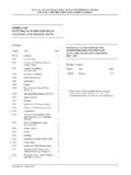
8 The specified serviceable life of the steps should be the same as that identified for the equipment to which the steps are providing access. The loading requirements should be identified for the specific use of the steps and be within the limits stated in BS EN ISO 14122-3 section (02/17) Table 11/1 gives some material requirements, these are minimum default values and should be supplemented with site specific requirements in CONTRACT specific Appendix 11/2. The compiler should include site specific requirements for each material to be used and reference relevant Clauses, or numbered appendices, that are not already referenced in Table 11/1. For example, for concrete the type of specification should be determined, designed, prescribed or standardised prescribed, along with the basic and other requirements such as concrete designation, maximum aggregate size, consistence class, compressive strength, and other limiting values for composition.
9 Specific relevant Clauses of Series 1700 should be identified and referenced. Where details may be given in Series 1700 CONTRACT specific Appendices these should be cross-referenced in CONTRACT specific Appendix 11/2. Where the Contractor is to design the access steps site details should be stated to inform the design and set any other relevant minimum requirements. Volume 2 Series NG1100 Notes for Guidance on the Specification for Highways Works Kerbs, Footways and Paved AreasAmendment November 2004 A1[Note to compiler: This should include:]1 (11/04) Dimensions, type designations and performances and classes [see clause and the National Annex NA of BS EN 1340] of precast concrete kerbs, channels, edgings and quadrants [ ].
10 2 Dimensions of precast concrete kerbs to be bonded to the pavement surface [ ].3 Details of kerb joints at bridge expansion joints designed by the Overseeing Organisation [ ].4 (11/04) Dimensions of in-situ asphalt kerbing [see MCHW 3 (HCD) Drawing Nos. B9 and B10] or in-situ concrete kerbing, channels and edgings [ , ].5 Concrete curing requirements if different from Clause 1027 [ ].6 (11/04) Type designation, thickness and performances and classes of precast concrete flags or natural stone flags [ ]. [For precast concrete flags see clause , the National Annex NA of BS EN 1339. For natural stone flags, see relevant clauses and the National Annex NA of BS EN 1341.]7 (05/01) Details of required bond for flags or natural stone flags [ ].