Transcription of Manual: 7 Series Flame Arrestor - Emerson
1 North America OnlyD103829X012 Instruction ManualFebruary 20157 1. 7 Series Flame Arrestor7 Series Flame ArrestorTable of ContentsIntroduction ..1 Specifications ..2 Principle of Operation ..3 Factors Affecting Flame Arrestor Performance ..3 Installation ..5 Maintenance ..6 Recommended Spare Parts ..10 Parts Ordering ..10 Parts 10 WARNiNG!Failure to follow these instructions or to properly install and maintain this equipment could result in an explosion, fi re and/or chemical contamination causing property damage and personal injury or fl ame arrestors must be installed, operated and maintained in accordance with federal, state and local codes, rules and regulations and Emerson Process Management Regulator Technologies Tulsa, LLC (EmersonTM) a qualifi ed service person to service the unit.
2 Installation, operation and maintenance procedures performed by unqualifi ed person may result in improper adjustment and unsafe operation. Either condition may result in equipment damage or personal injury. Only a qualifi ed person shall install or service the 7 Series fl ame of the ManualThis Instruction manual provides specifi cations, installation and maintenance instructions and parts ordering information for the 7 Series fl ame Description7 Series fl ame arrestors are designed to stop the propagation of confi ned low pressure defl agration. The 7 Series is typically used for end-of-line and near-end-of-line applications when the system operating pressure is near atmospheric levels and when there is minimal probability of a fl ame stabilizing on the fl ame Arrestor element for an extended with fl anged connections, this Arrestor allows removal of the fl ame cell element for easy cleaning and replacement without removing the Arrestor body from the pipe connection.
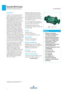
3 Standard housing construction is aluminum, carbon steel or North America Only7 Series27/--7 Series Housing SizeConnection SizeNECH ousing MaterialElement MaterialConnection TypeOptionsBlank = ConcentricE = Eccentric04 = 4 in. through 72 = 72 = 1 in. through 36 = 36 GroupBCDA = AluminumC = Carbon steel4 = 304 SST6 = 316 SSTH = Hastelloy E = ExoticA = Aluminum4 = 304 SST6 = 316 SSTH = Hastelloy E = ExoticF = Flat face flangeR = Raised face flange1 = Drain Port2 = Pressure Tap 3 = Temperature Probe Tap4 = Miscellaneous5 = Protective Coating6 = Special FeatureFigure 2. 7 series flame arrestor Available Constructions and Model Numbering SystemHastelloy is a mark owned by Haynes International, The Specifications section lists the specifications for the 7 Series .
4 Specification is stamped on the nameplate attached to the Flame ConstructionSee Table 1 and Figure 2 Gas GroupB, C and D Flange Size and Rating1 to 36 in. / 25 to 900 mmCL150 FF and RF Housing Size4 to 72 in. / 100 to 1800 mmTemperature Rating of Gaskets(1) Fiber Gaskets (standard): 450 F / 232 C Graphite Gaskets (Optional): Higher temperature1. The pressure/temperature limits in this Instruction manual and any applicable standard or code limitation should not be LengthSee Table 4 Housing MaterialAluminum, Carbon steel, 304 Stainless steel, 316 Stainless steel and Hastelloy Cell MaterialAluminum, 304 Stainless steel, 316 Stainless steel and Hastelloy Figure 3.
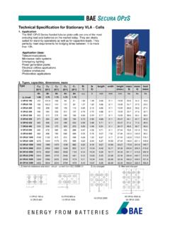
5 Flame Arrestor OperationFLAME STABILIZED ONARRESTOR ELEMENTPIPINGEXPOSED SIDEFLAME Arrestor ELEMENT ABSORBSAND QUENCHES Flame FRONTPROTECTED SIDEN orth America Only37 Seriesstainless steel. The element is available in stainless steel. Special material and protective coating are available on of OperationFlame Arrestor allows gas to pass though it but stops Flame in order to prevent a larger fire of explosion. Arrestor prevents Flame by absorbing and dissipating the heat from Flame as it attempts to travel through the spiral wound crimped ribbon Flame cells. These cells allow maximum flow with maximum Affecting Flame Arrestor PerformanceGas GroupWARNiNG!
6 Methanol is classified by the National Electrical Code (NEC) as a Group-D vapor. However, our lab tests indicate that methanol exhibits characteristics unlike other Group-D vapors under certain conditions. We therefore recommend that an Arrestor rated for Group-C vapors be specified for methanol 1. 7 Series Available Construction7 Series iN-LiNE Flame Arrestor CARbON STEEL AND STAiNLESS STEEL HOuSiNGS CONSTRuCTiONModelFlange SizeHousing Series iN-LiNE Flame Arrestor ALuMiNuM HOuSiNG CONSTRuCTiONModelFlange SizeHousing 508200708033 758200708044 1008200710066150102507120661501230071408 8200143507160882001640072010102502050072 2121230022550724121230024600 North America Only7 Series4 The type of gas in the system determines its gas grouping and therefore predetermines the type of Arrestor element required.
7 The element must be designed to accommodate the specific gas group that could possibly ignite and propagate in the system. The more explosive gases require the Flame cell to absorb the heat more quickly and efficiently. The National Electrical Code (NEC) groups gases into A, B, C, D and categories depending on the Maximum Experimental Safe Gap (MESG) of the Experimental Safe Gap (MESG)WARNiNG!Verify that the Flame Arrestor being installed has the appropriate gas group rating for your process. This information is shown on the nameplate attached to the element housing. Do not remove or alter this measurement of the maximum gap between two equatorial flanges on a metal sphere that will prevent a Flame from being transmitted from the sphere to the surrounding flammable mixture.
8 MESG is dependent on gas composition. The stoichiometric mixture (the ideal air/fuel ratio for the most efficient combustion) is used to determine the minimum MESG for a given gas. See Table 2 for the MESG per gas initial Operating PressureThis is the pressure of the system at or near static flow conditions. High pressure deflagration can occur more easily at higher system operating pressures than at pressures near atmospheric. Elevated pressures condense the ignitable gas giving the Flame more matter and energy to release thereby boosting the Flame heat intensity. Verify that your system pressure at or near static flow conditions does not exceed the maximum pressure shown on the Arrestor s name burn TimeWARNiNG!
9 Unlimited burning should not be allowed in any Flame Arrestor , regardless of its burn time rating. if burning can occur for a period exceeding 2 minutes starting at ambient temperature, it is recommended that a temperature alarm and shutdown system be burn time is the time it takes for a stabilized Flame , at greatest heat saturation conditions, to heat the Arrestor element above the auto-ignition temperature of the process gas stream resulting in Flame propagation through the Arrestor . See Table 3 for the 7 Series endurance burning 2. Maximum Experimental Safe Gap (MESG)NATiONAL ELECTRiCAL CODE (NEC)MESGTEST GAS 3. 7 series flame arrestor Endurance Burn Time GAS GROuP MAxiMuM iNiTiAL PRESSuREENDuRANCE buRN TiMEpsiakPaD minutes (Steel and Stainless steel models up to 12 in.)
10 And under)D minutes (all other Group-D) minutesNorth America Only57 SeriesTable 4. 7 Series Pipe Length RulesGAS GROuP b GAS GROuP C GAS GROuP D Maximum length of pipe between the Flame Arrestor and the ignition source without bends or other ft. / m., open ended pipe6 ft. / 2 m., open ended pipe20 ft. / 6 length of pipe between the Flame Arrestor and the ignition source with a maximum of one 90 bend. Multiple bends or any additional obstructions are not Recommended With a ft. / 2 m., open ended pipe20 ft. / 6 LengthsExtended lengths of pipe allow the Flame to advance into more severe states of Flame propagation such as high pressure deflagration or detonations.