Transcription of Material Processing Technology for Soft Ferrites …
1 American Journal of Materials Science 2012, 2(6): 165-170 DOI: Material Processing Technology for soft Ferrites manufacturing Deepak Bhalla1, *, DK. Singh2, Swati Singh1, Dipti Seth3 1 ACME College of Engineering, Muradnagar, Ghaziabad, India 2 Mechanical Engg Deptt, MMM Engineering College, Gorakhpur, India 3 Deptt of Applied Sciences, Raj Kumar Goel Engineering College Pilkhuwa, Ghaziabad, India Abstract In this paper efforts have been made to explain the manufacturing method of Manganese-Zinc (Mn-Zn) soft Ferrites in detail along with its uses and applications. The same method is applicable to Nickel-Zinc (Ni-Zn) and Lithium Titanium (Li-Ti or Microwave) Ferrites also. A process flow chart is shown. The manufacturing steps like-mixing of powders, calcination of powder, grinding of powder, granules making, pressing of components, sintering in tunnel kiln or box furnace and machining on rotary table grinding machine, have been explained.
2 Effect of atmosphere (oxygen), when the components are sintered at high temperature, is discussed. The temperature profiles of muffle furnace and tunnel kilns have also been discussed. The variation in temperature within the muffle furnace (900 900 800 mm) has been studied with the help of a sliding thermocouple. Temperature gradient within the furnace volume has been plotted on graph. A mathematical relation has been found using curve fitting equation. Actual and mathematical results have been compared. Keywords soft Ferrites , Processing , Temperature, Furnace, Sintering 1. Introduction Ferrites are dense homogeneous ceramic materials used, as a core, in the transformers, for electronics devices. Ferrite cores are also used as inductors and electromagnets in elec-tro-mechanical and electronic industries. The operating frequency range of these transformers may vary from 100 Hz to Giga Hz, or even more. These are rigid and brittle in nature.
3 These are expressed by the molecular formula MFe2O4 (where M is an Oxide of Divalent Metal). When Ferrite contains two or more metal ions in M Positing, then it is called mixed ferrite. Such as Manganese Zinc (Mn-Zn) & Nickel Zinc (NI-Zn). Ferrites have a paramount advantage of bearing better properties such as high electrical resistivity resulting in low eddy current losses, over a wide frequency range in com-parison with other types of magnetic materials. Other char-acteristics are high permeability and temperature stability, low cost, low volume (occupies less space), high stability temperature, humidity & pressure. The intricate geo-metrical shapes are possible to for larger production. The color of Ferrites may be silver gray or black. The mechanical and electromagnetic properties of Ferrites can be affected by operating process conditions such as raw mate-rial composition, temperature, sintering atmosphere, * Corresponding author: (D.)
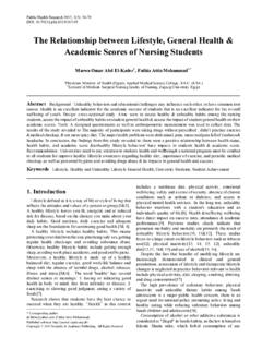
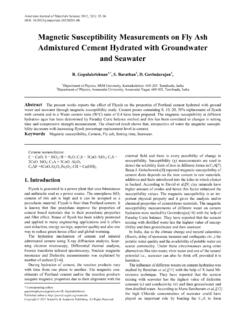
4 Bhalla) Published online at Copyright 2012 Scientific & Academic Publishing. All Rights Reserved compacting pressure, type of grinding and machining etc. There are two types of Ferrites - (i) soft Ferrites and (ii) Hard Ferrites (permanent magnets). A few soft ferrite components are shown below: Figure 1. Ferrite Components The importance of soft ferrite is obvious as it appears in the wide range of applications, such as -TV transformer cores, mobile phone cores, land line phones, railways axle counters, loud speakers/music systems, high db loss materi-als for microwave ovens, electronic transformers, as a core, being used for high frequency applications ranging from100 Hz to giga Hz, adjustable inductors, magnetic circuits for low & high power applications, energy meters, wave-guide and antenna of radar, strategic defence application like mi-crowave Ferrites used in phase shifters (for missiles) and radar antenna.
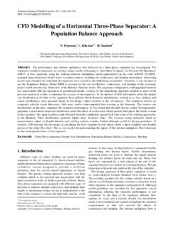
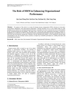
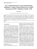
5 As per Hitoshi Saita[1] the Mn-Zn based magnetic ferrite Material has heretofore been used mainly as a transformer 166 Deepak Bhalla et al.: Material Processing Technology for soft Ferrites manufacturing Material for a communication apparatus and a power supply. Different from other magnetic ferrite materials, the Mn-Zn based magnetic ferrite Material is characterized in that it has a high saturation magnetic flux density, permeability is also high, and power loss is small during the use as the trans-former, and the addition of SiO2, CaO can lower the power loss. Moreover, various additives are studied for a purpose of further reduction of the power loss. However, the power loss is largely influenced by a slight amount of impurities contaminated during the manufacture process of the magnetic ferrite Material , or a slight amount of impurities contained in a raw Material . 2. Experiments The following are the main steps involved in manufac-turing of soft ferrite components: Powder mixing Pre sintering Wet grinding of powders Spray drying Pressing of homogenous mixture to obtain desired shape Sintering in tunnel type furnaces (temp 1400 C) Machining of sintered product to obtain end product.
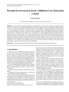
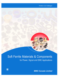
6 A typical flow chart of soft ferrite manufacturing is shown below: Figure 2. Process steps of soft ferrite manufacturing It was found that weight wise loss of Material from raw Material mixing to the recovery of sintered components, was of the order of 50%. Of course overall process loss up to 20% is inevitable[2]. Mixing of Powders In mixing operation, salts of metals (in the form of oxides or carbonates) are checked for purity (in ppm) by the chemical analysis. High purity raw materials are needed to manufacture ferrite cores, so that these yield good me-chanical and magnetic properties. Wet mixing (Water used as a media) for 2 kg batch is done with following details: (i) Weight of dry powders (iron oxide, manganese di-oxide and zinc oxide) = kg. (ii) Weight of de-ionized water = 5 kg (iii) Mixing time = 8 Hrs After 8 hrs. of mixing, the slurry is dried into oven at 150 C for overnight which gives dry & mixed powder.
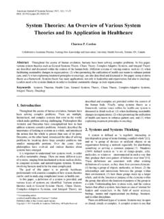
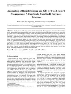
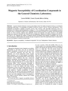
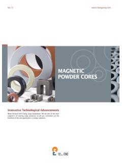
7 Fig-ure 3 shows the mixing method. g MotorFerric oxide+MnO2+ZnO2 Figure 3. Ball mill for wet (de-ionised water based) mixing of powders and grinding Calcination of Powders After mixing, the powder is calcined (pre-heated) at a temperature around 75% of final sintering temperature. Few manufacturers are converting powder into small pallets to save process loss during calcination. Calcination is a pre firing process in which the powder temperature is raised to approximately 940 C (for a typical Mn-Zn ferrite composi-tion) in air atmosphere. During calcination the carbonates are converted into oxides, the impurities get evaporated and the shrinkage at final product is reduced to 17 to 18% instead of 20 to 21%, this reduces the possibility of cracks formation during cooling of sintered product. A schematic diagrame of calcination is shown in Figure. 4, where a ratary kiln is being used.
8 Powder is fed from one end through hopper and is being collected after passing through the kiln. 10 Temp 9500 CCalcined Powder Figure 4. Calcination (Pre-sintering) in rotary kiln Grinding Wet grinding is performed in the ball mill as shown in Figure. 3. This operation is similar to wet mixing with the only difference that the ball-mill running time is 20 to 24 hours, instead of 8 hrs, to ensure the particle size reduction to 2 to 16 m. After wet grinding, the slurry is dried-up in the oven. Calcined (prefired) and sintered M-Zn Ferrites could achieve the maximum density ( g/cm3), and the average grain size was 8-10 m. with pure ferrite phase. Flavin E.[3] stated that high frequency permeability is dependent on the particle size. American Journal of Materials Science 2012, 2(6): 166-170 167 Granules Making From this fine, mixed and dried ferrite powder, granules are prepared by hand or by spray drier.
9 For 200 kg batch granules are made using spray drier and for smaller batches granules are made manually. 12 Compressed airHot airSpray Drier ChamberTemp 3500 GranulesLiquid SlurryPumped In G a u es Figure 5. Spray drying for preparing granules While using spray drier, ferrite slurry is passed through a two fluid nozzle as shown in Figure. 5. Poly vinyl alcohol (PVA) is used as a binder. The glycerin is used for lubrication and water is used to provide some moisture. All these ingredients are homogeneously mixed separately. For a batch size of 200 kg. amount of additives are as below: Poly Vinyl Alcohol = Kg. Water / Spirit = Kg. Glycerin = Kg. Mesh size of granules = 40 to +150 (British Standard Grit Size). The above combination is added slowly and in two or three steps into the ferrite powder. The powder is rigorously mixed in Attritors to form the slurry. Then the Material is passed through the mesh -40 and +150 grit size.
10 Thus, powder particles are converted into granules. 13 PressDie of Required ComponentComponent being Pressed Figure 6. Press for compacting powders Pressing The next step is forming of the component. Forming or pressing is done on mechanical, hydraulic or isostatic press. The capacity of press ranges from 2 tons to 100 tons de-pending upon cross section area of the component. The pressure is kept from 1 ton to ton per cm square. During pressing the desired shape of component is obtained. The rods may be pressed by extrusion method also. Pressing in a closed die is done using simultaneous action of top and bottom punches in die cavity such that uniform density is obtained. With the help of press tool assemblies, very complex core shapes can be pressed. The height of green component can be adjusted by changing the die-fill. As per Dietmar Holz.[4] the homogeneity of the density profile along the compact, is related to the chance of crack devel-opment and product deformation during sintering this ob-viously means deterioration in its density and permeability.