Transcription of MECHANICAL PROPERTIES OF MATERIALS - MIT
1 MECHANICAL PROPERTIES OF MATERIALSD avid Roylance20082 Contents1 Uniaxial MECHANICAL StiffnessinTension-Young ThePoissonEffect .. ShearingStressesandStrains .. Stress-StrainCurves .. Problems .. 232 Thermodynamics of MECHANICAL EntropicResponse .. Problems .. MATERIALS .. Problems .. 484 General Concepts of Stress and Kinematics:theStrain Equilibrium: the Stress ConstitutiveRelations .. Problems .. 785 Yield and Plastic MultiaxialStressStates .. TheDislocationBasisofYieldandCreep .. Kinetics of Creep in Crystalline MATERIALS .. Problems .. AtomisticsofCreepRupture .. FractureMechanics-theEnergy-BalanceAppro ach .. TheStressIntensityApproach .. Fatigue .. Problems ..128 Chapter 1 Uniaxial MECHANICAL ResponseThis chapter is intended as a review of certain fundamental aspects of mechanics of MATERIALS , usingthe material s response to unidirectional stress to provide an overview of MECHANICAL propertieswithout addressing the complexities of multidirectional stress states.
2 Most of the chapter willrestrict itself to small-strain behavior, although the last section on stress-strain curves will previewmaterial response to nonlinear, yield and fracture behavior as Tensile Strength and Tensile StressPerhaps the most natural test of a material s MECHANICAL PROPERTIES is thetension test,in whicha strip or cylinder of the material , having lengthLand cross-sectional areaA, is anchored at oneend and subjected to an axial loadP a load acting along the specimen s long axis at theother. (See Fig. ). As the load is increased gradually, the axial deflection of the loaded endwill increase also. Eventually the test specimen breaks or does something else catastrophic, oftenfracturing suddenly into two or more pieces. ( MATERIALS can fail mechanically in many differentways; for instance, recall how blackboard chalk, a piece of fresh wood, and Silly Putty break.) Asengineers, we naturally want to understand such matters as how is related toP, and what ultimatefracture load we might expect in a specimen of different size than the original one.
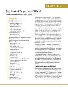
3 As materialstechnologists, we wish to understand how these relationships are influenced by the constitution andmicrostructure of the : The tension of the pivotal historical developments in our understanding of material MECHANICAL proper-ties was the realization that the strength of a uniaxially loaded specimen is related to the magnitudeof itscross-sectional area. This notion is reasonable when one considers the strength to arise from56 CHAPTER 1. UNIAXIAL MECHANICAL RESPONSEthe number of chemical bonds connecting one cross section with the one adjacent to it as depicted inFig. , where each bond is visualized as a spring with a certain stiffness and strength. Obviously,the number of such bonds will increase proportionally with the section s area1. The axial strengthof a piece of blackboard chalk will therefore increase as thesquareof its diameter. In contrast,increasing thelengthof the chalk will not make it stronger (in fact it will likely become weaker,since the longer specimen will be statistically more likely to contain a strength-reducing flaw.)
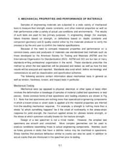
4 Figure : Interplanar bonds (surface density approximately 1019m 2).When reporting the strength of MATERIALS loaded in tension, it is customary to account for theeffect of area by dividing the breaking load by the cross-sectional area: f=PfA0( )where fis theultimate tensile stress,often abbreviated as UTS,Pfis the load at fracture, andA0is the original cross-sectional area. (Some MATERIALS exhibit substantial reductions in cross-sectionalarea as they are stretched, and using the original rather than final area gives the so-callengineeringstrength.) The units of stress are obviously load per unit area, N/m2(also called Pascals, or Pa)in the SI system and lb/in2(or psi) in units still used commonly in the United many design problems, the loads to be applied to the structure are known at the outset, and we wishto compute how much material will be needed to support them. As a very simple case, let s say we wish touse a steel rod, circular in cross-sectional shape as shown in Fig.
5 , to support a load of 10,000 lb. Whatshould the rod diameter be?Directly from Eqn. , the areaA0that will be just on the verge of fracture at a given loadPfisA0=Pf fAll we need do is look up the value of ffor the material , and substitute it along with the value of 10,000lb forPf, and the problem is number of MATERIALS PROPERTIES are listed in theMaterials Properties2module, where we find the UTSof carbon steel to be 1200 MPa. We also note that these PROPERTIES vary widely for given MATERIALS dependingon their composition and processing, so the 1200 MPa value is only a preliminary design estimate. In lightof that uncertainty, and many other potential ones, it is common to include a factor of safety in the1 The surface density of bondsNScan be computed from the material s density ,atomicweightWaand Avogadro snumberNAasNS=( NA/Wa)2/3. Illustrating for the case of iron (Fe):NS= 23= 1015atomscm2NS 1015atomcm2is true for many TENSILE STRENGTH AND TENSILE STRESS7 Figure : Steel rod supporting a 10,000 lb Selection of an appropriate factor is an often-difficult choice, especially in cases where weight or costrestrictions place a great penalty on using excess material .
6 But in this case steel is relatively inexpensiveand we don t have any special weight limitations, so we ll use a conservative 50% safety factor and assumethe ultimate tensile strength is 1200/2 = 600 now have only to adjust the units before solving for area. Engineers must be very comfortable withunits conversions, especially given the mix of SI and older traditional units used today. Eventually, we lllikely be ordering steel rod using inches rather than meters, so we ll convert the MPa to psi rather thanconvert the pounds to Newtons. Also usingA= d2/4 to compute the diameter rather than the area, wehaved= 4A = 4Pf f= 4 10000(lb) 600 106(N/m2) 10 4 lb/in2N/m2 12= inWe probably wouldn t order rod of exactly in, as that would be an oddball size and thus too 3/8 ( in) would likely be a standard size, and would be acceptable in light of our conservativesafety the specimen is loaded by an axial forcePless than the breaking loadPf,thetensile stressis defined by analogy with Eqn.
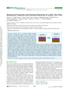
7 As =PA0( )The tensile stress, the force per unit area acting on a plane transverse to the applied load, is afundamental measure of the internal forces within the material . Much of Mechanics of Materialsis concerned with elaborating this concept to include higher orders of dimensionality, working outmethods of determining the stress for various geometries and loading conditions, and predictingwhat the material s response to the stress will engineering applications, notably aerospace vehicles, require MATERIALS that are both strong andlightweight. One measure of this combination of PROPERTIES is provided by computing how long a rod of thematerial can be that when suspended from its top will break under its own weight (see Fig. ). Here thestress is not uniform along the rod: the material at the very top bears the weight of the entire rod, but thatat the bottom carries no load at compute the stress as a function of position, letydenote the distance from the bottom of the rod andlet the weight density of the material , for instance in N/m3, be denoted by.
8 (The weight density is relatedto the mass density [kg/m3]by = g,whereg= the acceleration due to gravity.) The weightsupported by the cross-section atyis just the weight density times the volume of materialVbelowy:8 CHAPTER 1. UNIAXIAL MECHANICAL RESPONSEF igure : Circular rod suspended from the top and bearing its own (y)= V= AyThe tensile stress is then given as a function ofyby Eqn. as (y)=W(y)A= yNote that the area cancels, leaving only the material density as a design length of rod that is just on the verge of breaking under its own weight can now be found by lettingy=L(the highest stress occurs at the top), setting (L)= f, and solving forL: f= L L= f In the case of steel, we find the mass density in Appendix A to be 103(kg/m3); thenL= f g=1200 106(N/m2) 103(kg/m3) (m/s2)= would be a long rod indeed; the purpose of such a calculation is not so much to design superlong rodsas to provide a vivid way of comparing Stiffness in Tension - Young s ModulusIt is important to distinguishstiffness,which is a measure of theloadneeded to induce a givendeformationin the material , from thestrength, which usually refers to the material s resistance tofailure by fracture or excessive deformation.
9 The stiffness is usually measured by applying relativelysmall loads, well short of fracture, and measuring the resulting deformation. Since the deformationsin most MATERIALS are very small for these loading conditions, the experimental problem is largelyone of measuring small changes in length a number of such measurements on long wires under various loads, and observedthat to a good approximation the loadPand its resulting deformation were related linearly aslong as the loads were sufficiently small. This relation, generally known asHooke s Law,can bewritten algebraically asP=k ( )wherekis a constant of proportionality called thestiffnessand having units of lb/in or not a function of the material alone, but is also influenced by the3 Robert Hooke (1635 1703) was a contemporary and rival of Isaac Newton. In the style of his time, Hookeoriginally published his observation as a Latin anagramceiiinossttuvfromut tensio, sic vis- As the extension, so STIFFNESS IN TENSION - YOUNG S MODULUS9specimen shape.
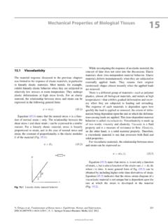
10 A wire gives much more deflection for a given load if coiled up like a watch spring,for useful way to adjust the stiffness so as to be a purely MATERIALS property is to normalize theload by the cross-sectional area; to use the tensile stress rather than the load. Further, thedeformation can be normalized by noting that an applied load stretches all parts of the wireuniformly, so that a reasonable measure of stretching is the deformation per unit length: = L0( )HereL0is the original length and is a dimensionless measure of stretching called more general measures of load per unit area and displacement per unit length4,Hooke sLawbecomes:PA0=E L0( )or =E ( )The constant of proportionalityE, calledYoung s modulus5or themodulus of elasticity6,isoneofthe most important MECHANICAL descriptors of a material . It has the same units as stress, Pa or shown in Fig. , Hooke s law can refer to either of Eqns. or : Hooke s law in terms of (a) load-displacement and (b) Hookean stiffnesskis now recognizable as being related to the Young s modulusEand thespecimen geometry ask=AEL( )4It was apparently the Swiss mathematician Jakob Bernoulli (1655-1705) who first realized the correctness of thisform, published in the final paper of his the English physicist Thomas Young (1773 1829), who also made notable contributions to the understandingof the interference of light as well as being a noted physician and a form of MATERIALS response that refers to immediate and time-independent deformation uponloading, and complete and instant recovery of the original geometry upon removal of the load.