Transcription of MELBOURNE RETAIL WATER AGENCIES - Pages - …
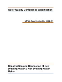
1 200 MIN250 RRJ PIPERRJ PIPESTEEL REINFORCING TABLE 205A-CFIGURE 205A-E: ELEVATIONFLUSHING / WASHOUT BEND thrust RESTRAINTFIGURE 205A-D: SECTION VIEWPLAIN thrust RESTRAINT FOR BENDSFIGURE 205A-B: SECTION VIEWPLAIN thrust RESTRAINT FOR TEESFIGURE 205A-I: - PLAN VIEW,IN LINE thrust RESTRAINTFIGURE 205A-C: PLAN VIEWPLAIN thrust RESTRAINT FOR BENDSFIGURE 205A-A: PLAN VIEWPLAIN thrust RESTRAINT FOR TEESDN-B-DDN250 MINTHRUSTRESTRAINTAREA (A)THRUSTRESTRAINT AREAA = 2A 1 + A 2 THRUSTRESTRAINTAREA (A)TIMBER/PLASTICTHRUST RESTRAINTCONCRETERESTRAINTFIGURE 205A-J: SECTION VIEW,VALVE AND INLINE thrust RESTRAINTFIGURE 205A-K: SECTION VIEW,VALVE AND HYDRANT WITH INLINE thrust RESTRAINTFIGURE 205A-F: VERTICAL BEND ELEVATION3 thick insertion rubber betweenstrap and bendStainless steelstrap (see detail)250 MINP rotrude restraint min250 into solid nativeground past both sidesof trenchVertical thrustHorizontal thrustFIGURE 205A-G:TYPICAL SS STRAP50 x 6 THICKGRADE 316 STAINLESSSTEELDIAMETERTO SUITPIPE3 x PIPE DIA50 FLANGED GATE VALVEFL-FL CONNECTORFLANGEDGATE 45 on Vertical Bend thrust bend thrust restraints and socket spigot joints are not permittedfor major crossings (refer to MRWA-W-210).
2 Bend restraints require WATER Agency restraint centrally around restraint into trench a minimum depth of concrete volumes in Table 205A-A are based on a test pressure of1000 205A-A: VERTICAL BENDCONCRETE RESTRAINT VOLUMES-HFIGURE 205A-H: ELEVATION,IN LINE CONCRETE thrust RESTRAINT A 2 A 1A 1 THRUSTRESTRAINTAREA (A 1)AREA UNDERTRENCH (A2)HYDRANTPUDDLE FLANGE. REFERMRWA-W-306 A & B .MIN 300 THRUSTRESTRAINTAREA (A1)MIN 150 MRWA WATER SUPPLY STANDARDSREVISION RETAIL WATER AGENCIESDATE:DATE:CHECKED:DRAWN:DESIGNED :126789101211345 HHCWWSEWLYVWDATENAMEAPPROVED:CWWSEWLYVWD ATENAMEAPPROVEDDATEDESCRIPTIONREVA126345 BCDAEFG12678910121135 ABCDEFGHMRWA-W-205 ANOT TO SCALE20123 SINGLE MAIN CONCRETE RESTRAINTSAND PE PIPE thrust RESTRAINTR. JAGGER05/04/2011D. TOLENTINO05/04/2011XC. RIVETTE23/03 PUBLISHED DRAFT FOR COMMENT12/07/11R.
3 JAGGER2 PUBLISHED FIRST ISSUE23/03/12R. JAGGER3 TABLE 205A-B & PE SHRINKAGE UPDATED1/12/16R. JAGGERFIGURE 205A-L: JUNCTION OF PE PIPE AND RRJsH--H75 25 THRUSTRESTRAINTAREA (A)> 800 VALVES >DN375 REQUIRE TRENCH FLOORCONCRETE SLAB (REFER FIG 206-H)200 MIN200 MINHYDRANT1000 MAXMIN1000 MAX>100 FSLMAX 300 PUDDLE FLANGENOTES on Steel thrust restraint reinforcement is to consist of mesh as per Table 205A-B and N10grade bar (as per AS/NZS 4671). reinforcement shall have 75 clear cover of concrete ( 25). there are 2 layers of reinforcement, maintain min 150 separation between reinforcement or tie in additional bars to ensure reinforcement is located within50 25 of pipe OD at all intersections of reinforcement and using RL (rectangular mesh) in longitudinal restraints , the main wire (thickercloser spaced wire) shall span the Regarding FIGURE 205A-E: thrust area is that required for a dead end.
4 Washout bends as shown are not suitable for end of lines likely to be used tocharge future stages. Refer mrwa-w-308 for requirements in this MRWA-W-306.> 2mMIN 150 FOR MAINS > ACCEPTABLE FORMAINS < DN150. NOTES on PE Pipe thrust Restraint Area = F / P (Test Pressure)F = Net Force (KN) = Force (Poisson's ratio effect) + Force (Temperature Effect), OR = Force (Temperature Effect) + Force due to dead end (if valve present).[the calculation spreadsheet available on \ Pages \standards\ WATER shall be used to calculatechanges in length, restraint forces & areas] designer shall specify the installation requirements at the junctions of all PE mains with shall be done by ensuring that no spigot ends retract from RRJs by more than can be done the length of main (although typically the main length will need to be very short (<5-10m) toavoid the need for shrinkage restraints altogether), & the PE mains temperature at the time of connecting to designer shall assume a main temperature at time of connection of 25 C when calculating PErestraint the restraint area is large (ie.)
5 >2m ), the designer shall calculate the size of the PE restraintsbased on 20 C and shall re-consider whether the AHBP assumed could reasonably be Contractor shall then limit the temperature of the PE main (at the time of constructing the RRJjunctions) to the temperature stated in the design at a cooler time of year, & restraints and RRJ junctions at a cooler time of day, (ie: early morning), & the pipe (except for RRJ junctions) and allowing the pipe to settle to the temperatureof the earth (ie: leave the main overnight) before constructing the restraints and RRJ RESTRAINT to MESH REQUIREMENTS1 Layer of RL1018 or 2 layers of None if Restraint is >400 thick,Otherwise 1 Layer of SL81 TABLE 205A-B: IN LINE RESTRAINT STEELREINFORCEMENT SELECTION (SINGLE MAIN)> 2 layers of to 1 Layer of SL8150 25 thrust Restraint AreaPoisson's Contraction(if PE main is under pressure)PE MAINSOC-SPIG MAINShut Valve Force(if PE main is underpressure & SOC -SPIGOT main is not)Shut Valve Force(if SOC - SPIGOT main is underpressure & PE main is not)Thermal Contractionof PE Main(if PE main is installed hot)ThermalExpansion ofPE Main(if PE main isinstalled cold)SOC - SPIGOTJ oint at Risk ofSeparationIn Line Concrete ThrustRestraint (Refer Fig 205A-H)
6 >100> 2mOTHER EXCAVATION EDGE> 2m> 2m250 to1000 OTHER EXCAVATION EDGEOTHER EXCAVATION EDGEOTHER EXCAVATION EDGEGENERAL thrust restraints shall have a minimum of 2m of solid undisturbed ground behindthe bearing plain restraints , maximum encasement around pipe is 180 . line thrust restraints shall have a minimum of 2m of solid undisturbed ground orcompacted crushed rock around the bearing area on both sides of the Reducers, it is acceptable to place an in line concrete restraint behind the pipesocket instead of around a puddle the thrust area of all thrust restraints against a clean face of a material with anAHBP > 50 soils have an AHBP < 50 kPa, restrained joints shall instead be used as not cast thrust restraints against loose sand or restraints shall not interfere with other services.
7 restraints maybe cast aroundsleeved gas services (as shown) where there is no reasonable mains shall be deflected away from the concrete restraint where practicable andminimum cover can be maintained above the gas grade N20 concrete or concrete restraints must be formed at the sides (ie: edges other than bearingsurface) using temporary formwork or sand pouring concrete against fittings place a membrane of polyethylene, PVC or feltbetween the fitting and concrete to prevent damage to the , bolts and nuts to be clear of concrete.